Coilover Installation
This has been my most expensive and most transformative repair/mod that I’ve made to date. It was worth the time and financial investment.
This guide isn’t intended to show you every last nut and bolt to complete the job, but rather act as a point of reference for the steps involved in the replacement. I tried my best to highlight important information as needed. Feel free to contact me if you think I missed something.
Why I Chose Coilovers
Factory replacements for the adjustable dampening shocks no longer exist for turbo Z31s. Since mine were long blown out, I installed the KYB KG5787A Gas-A-Just shock and 365056 Excel G strut combination with the “turbo adapter kit” that is suggested by both RockAuto and many Z car part retailers in December of 2019. It took 6 months after installation for problems to start cropping up, and I replaced them with Powertrix coilovers in December of 2020.
The Problems With KYB
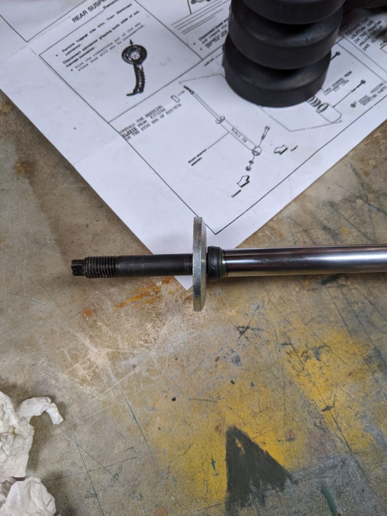
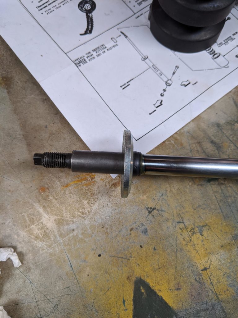
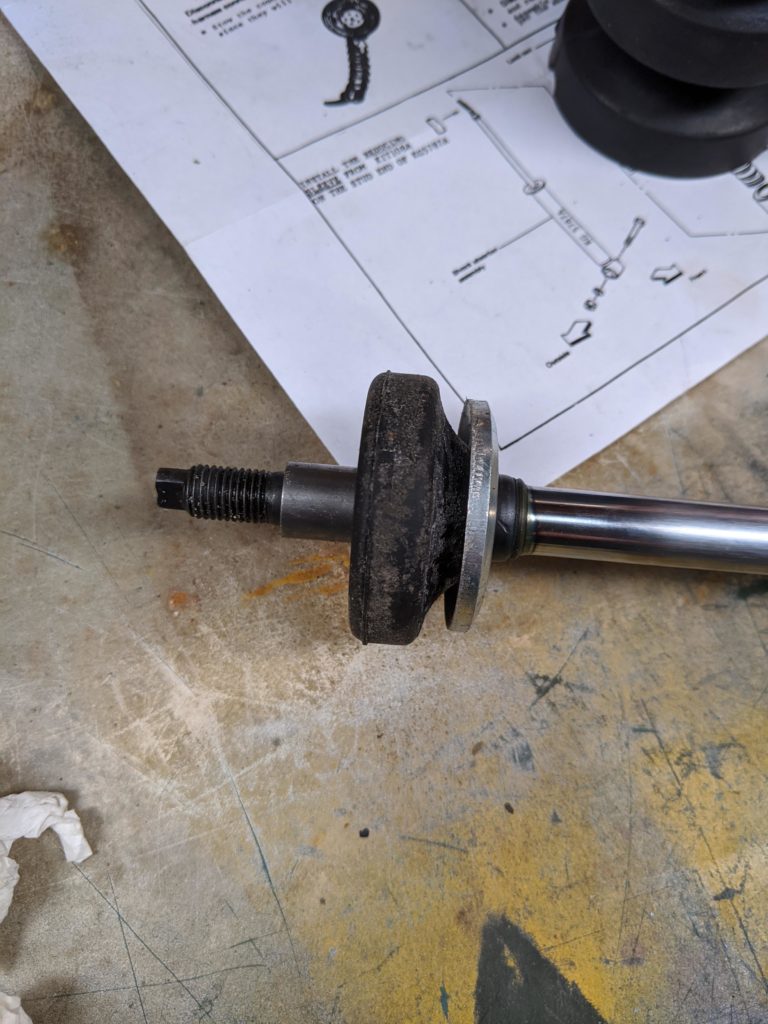
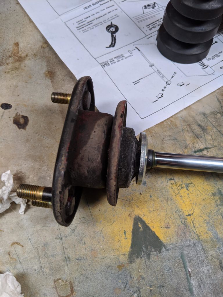
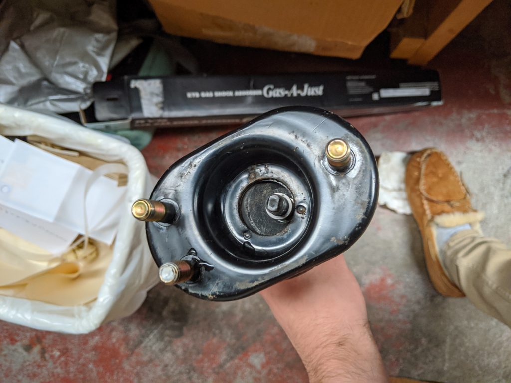
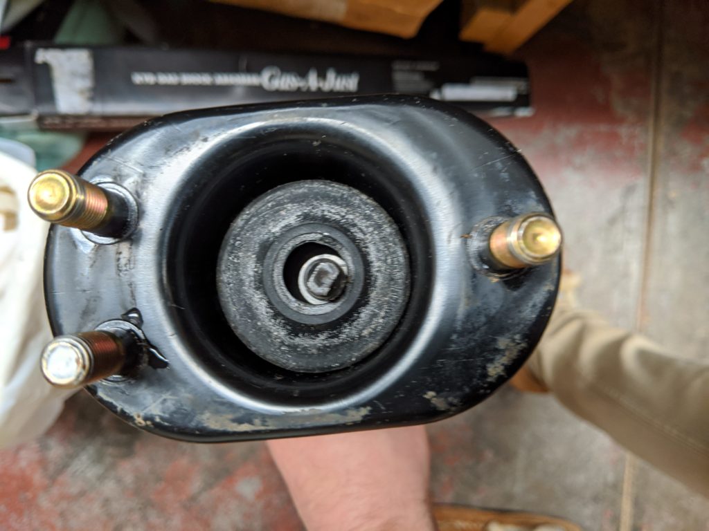
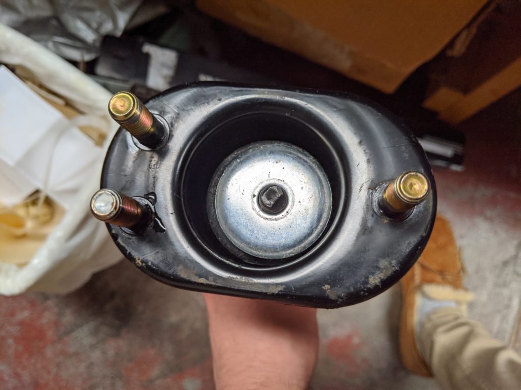
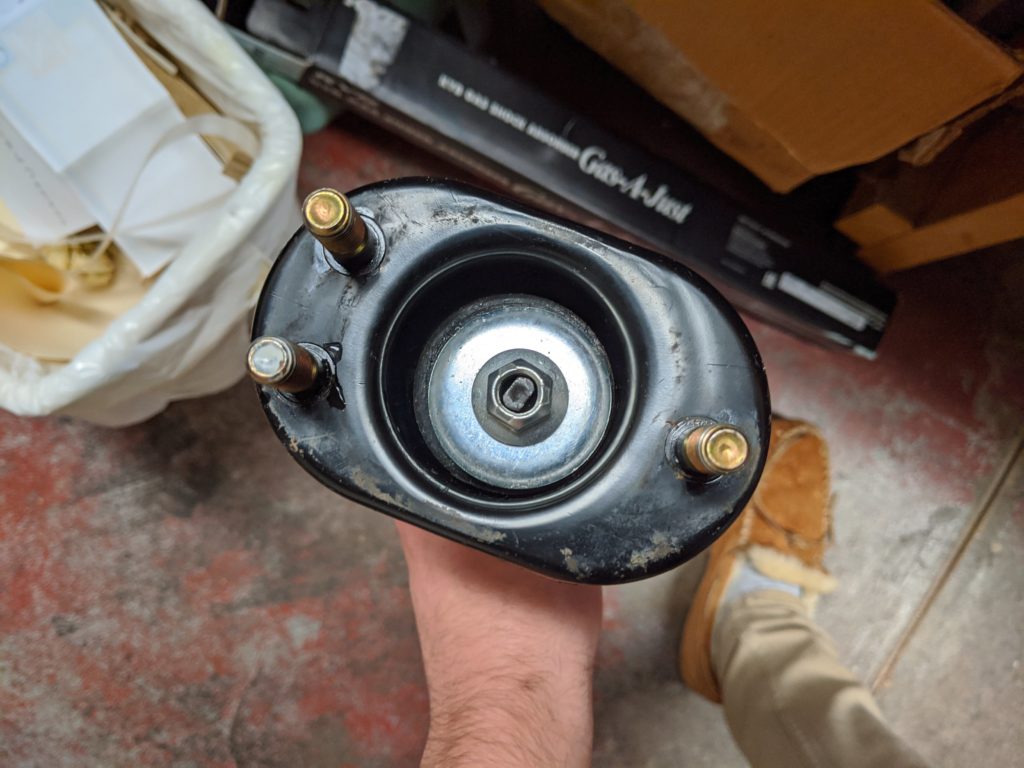
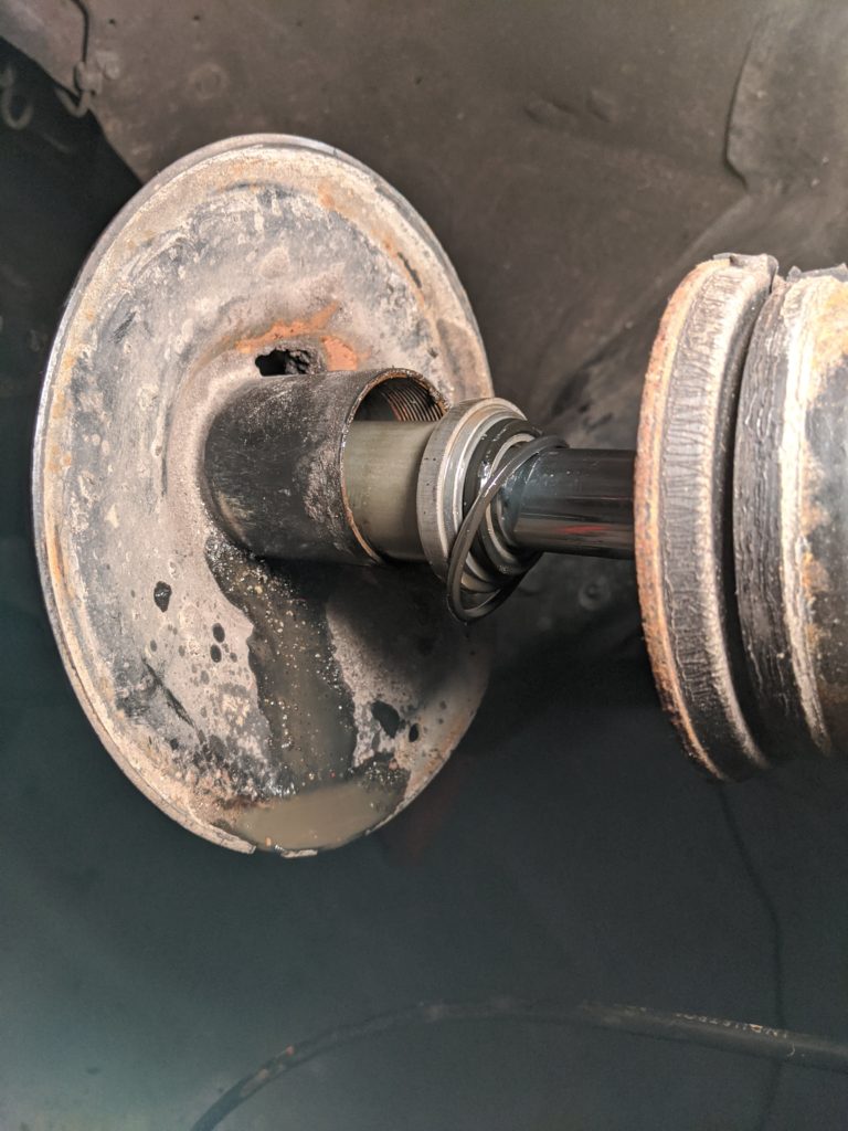
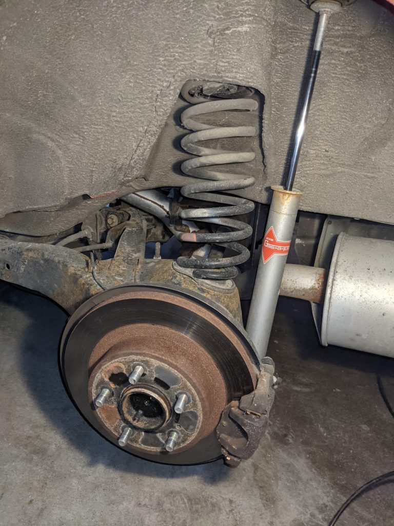
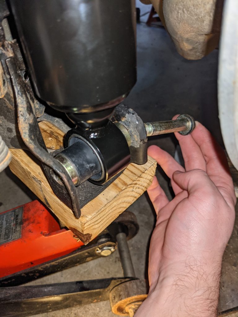
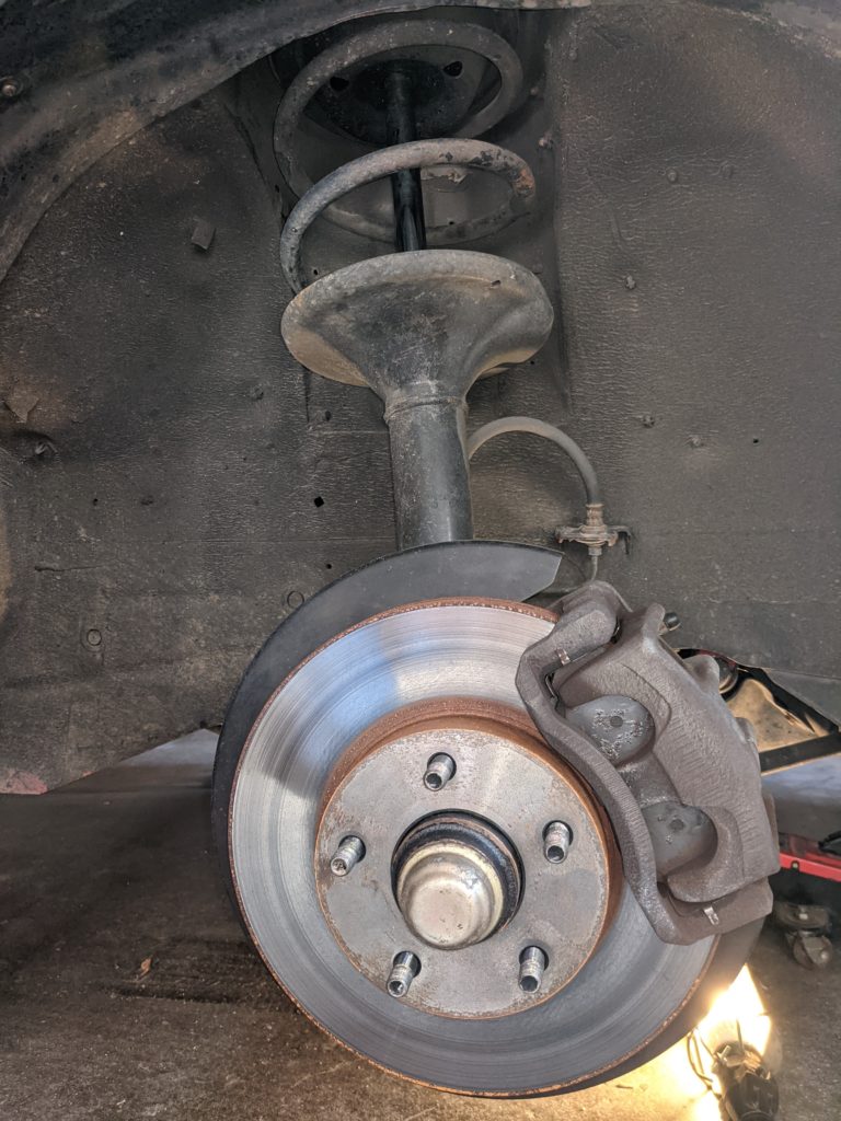
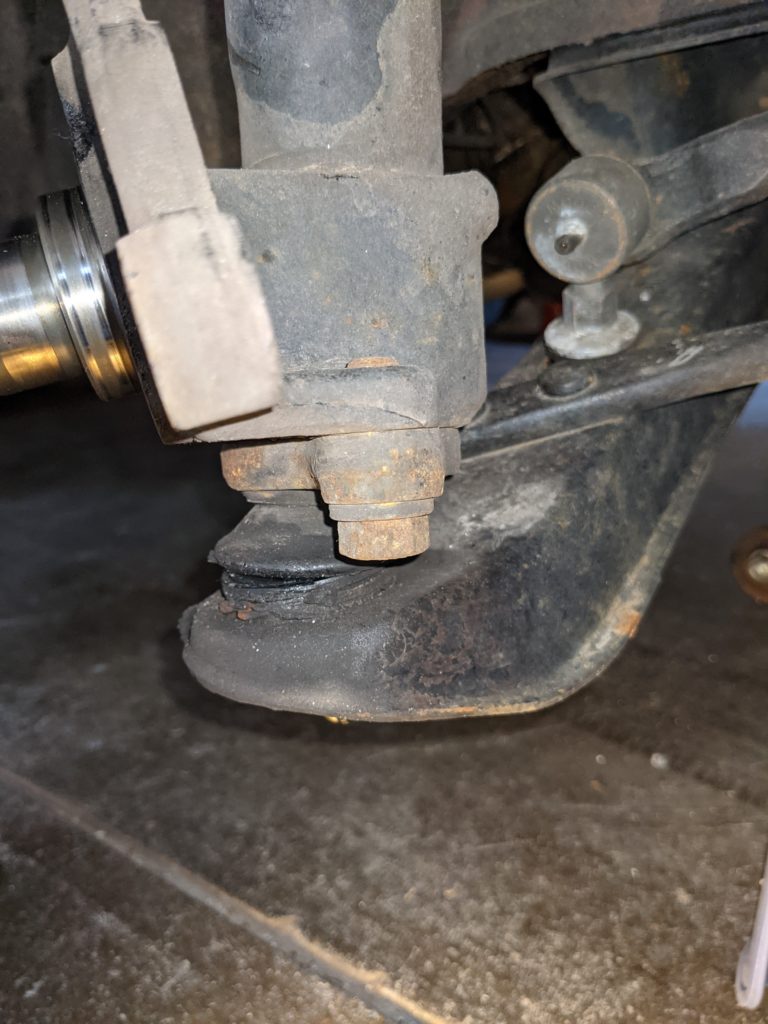
- Rear shock absorber mount was primitive and ineffective.
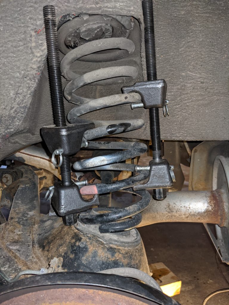
- As shown in the gallery to the right, the way in which the rear shock was held to the body of the car was by sandwiching the top of the shock’s arm between two thick rubber washers.
- This mount does not account for differences in angle along the suspension’s travel.
- The trailing arm configuration of the rear suspension means that these shocks regularly torqued forward and back while hitting bumps.
- Over the course of a year, it was obvious that road noise, dirt, and water were allowed to enter the cabin through the shock tower as the rubber was not able to deflect enough to keep up with the movement of the shock.
- Had this gone on long enough, I’m certain the car would have developed a significant corrosion problem on the shock towers.
- The front shocks were undersized for the tube that houses them.
- On turbo Z31s the front shocks had a larger diameter, likely to account for the adjustable valves and to house the fluid used by the shock itself.
- The KYB KG5787A were designed for naturally aspirated variants of this vehicle, meaning it had a much smaller outer diameter on the housing of the shock.
- Additionally, the length of the shock was too long to properly seat the gland nut that was responsible for holding the strut together.
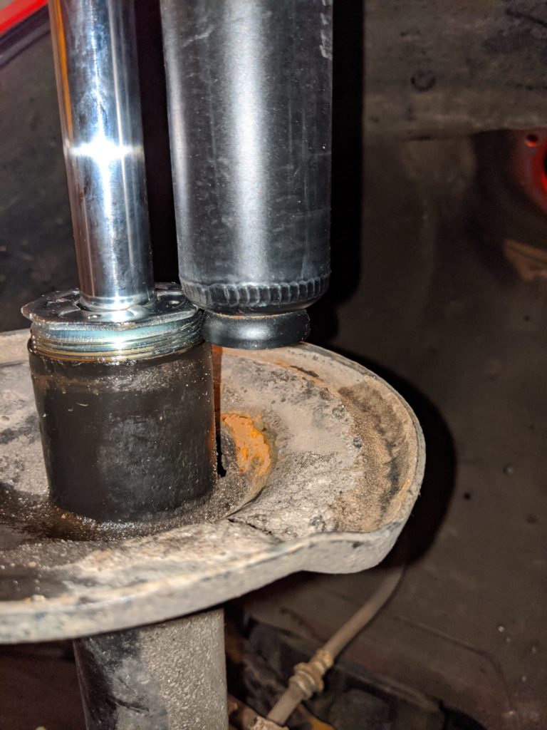
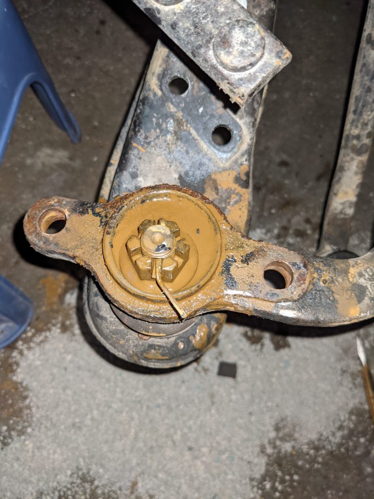
- I was not comfortable driving the car with only a few threads keeping the lower control arm attached to the strut tower, so I modified the Excel G shock by removing the bottom cup.
- Although this modification may have been responsible for the shock becoming dislodged within the strut tube over time, I see its presence as an even worse safety hazard.
- After 6 months of use, the shocks began banging around within the tube, causing quite the ruckus on brick roads.
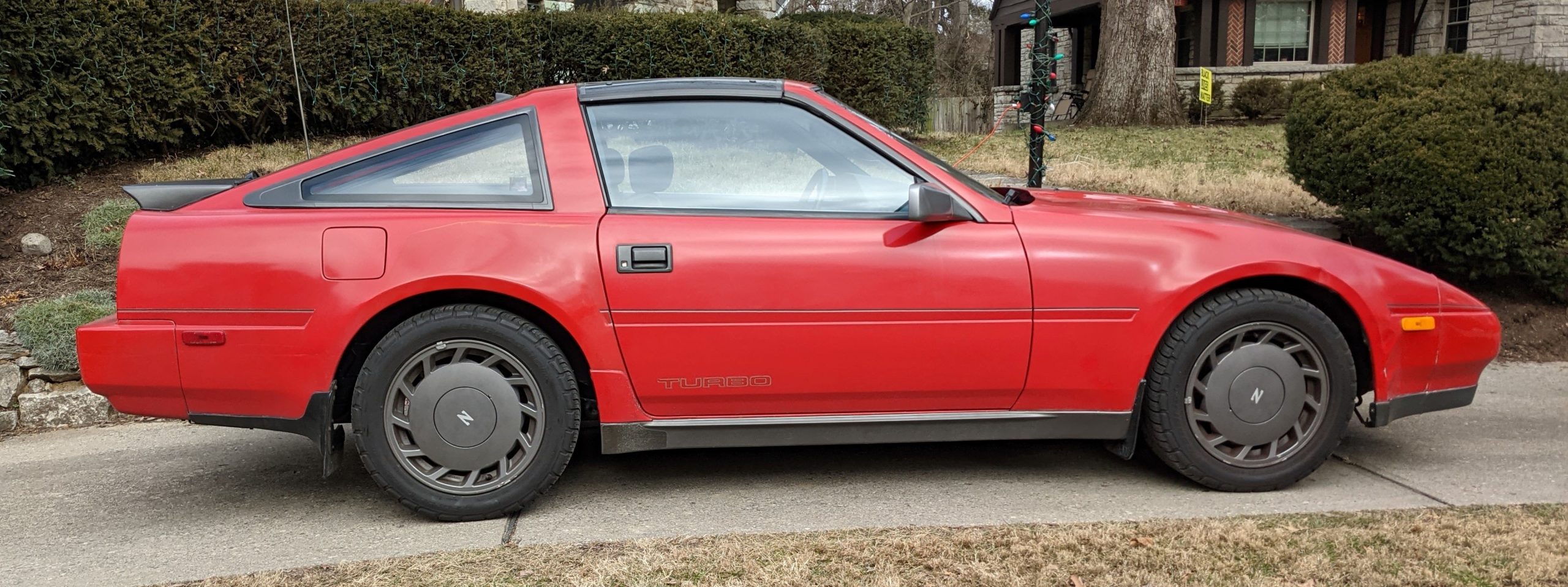
The Coilovers
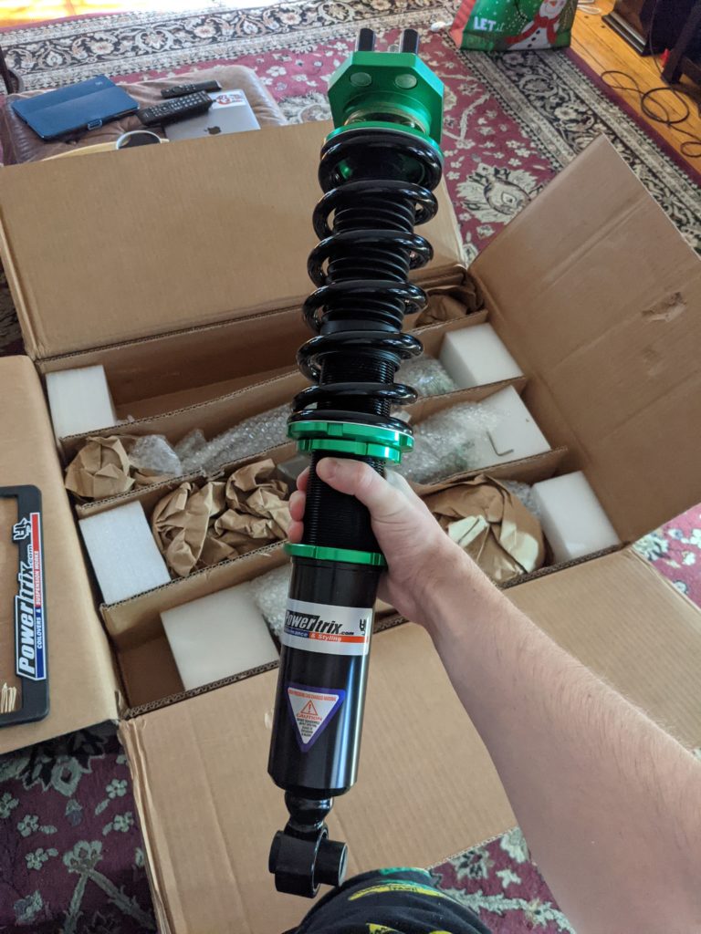
After much deliberation I settled on buying Powertrix coilovers. They are widely regarded as “the” coilovers to get for a Z31 and Powertrix regularly runs pre-order specials. This allows you to get a set for a few hundred dollars cheaper and split the payment in two, one payment to reserve a spot and a second when they are ready to ship.
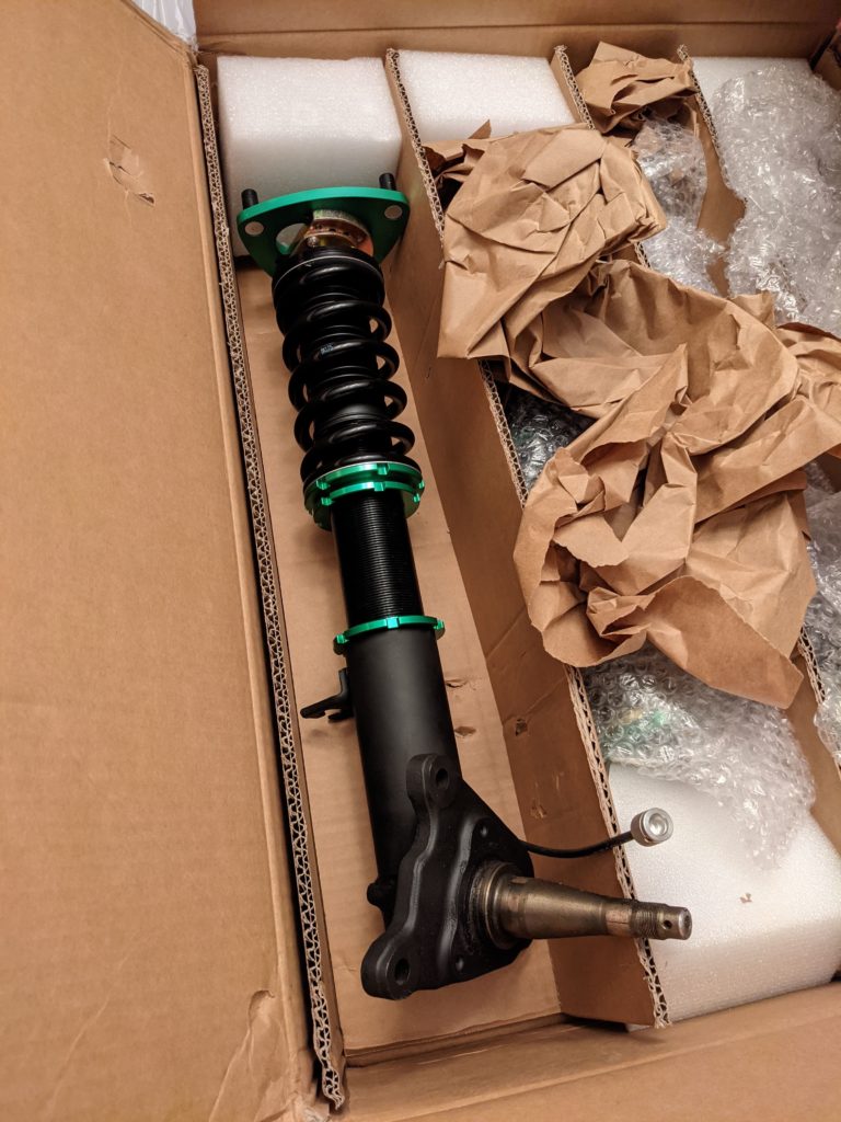
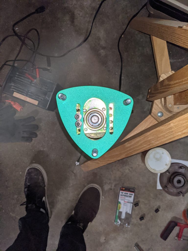
Since the front suspension uses a MacPherson strut, replacing the stock suspension with coilovers requires modification to the struts. To accomplish this, I took advantage of their spindle welding service which cost me a little over $200. The process was expensive and took a few weeks, but I got back a set of spindles that looked brand new and I could trust that the welding was done properly. I purchased a spare set of spindles from someone I met through a Z31 discord server so that I could have the welding/powder coating done while keeping my car on the road.
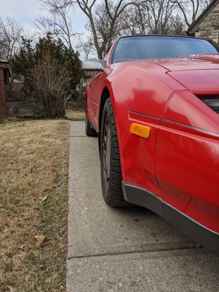
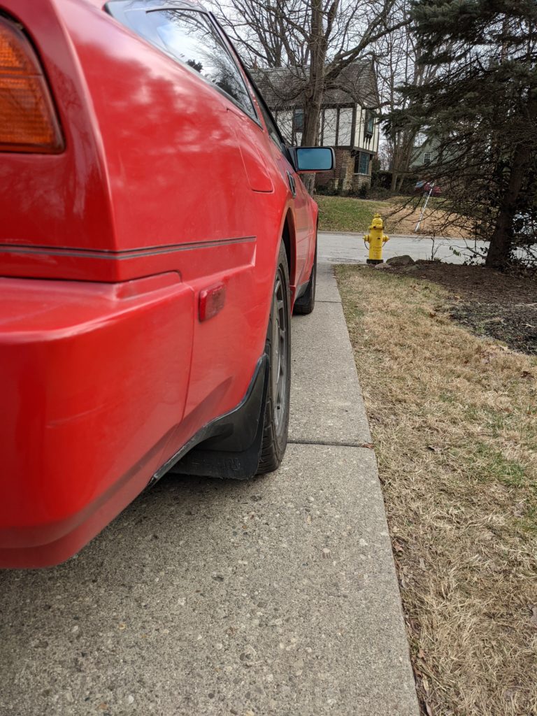
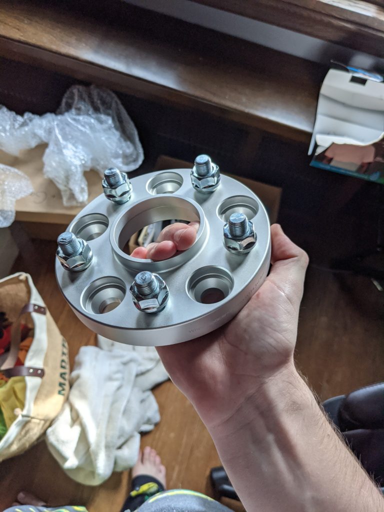
I also purchased a set of four 20mm wheel spacers from Powertrix. They claim that there is a small amount of interference with the coilover when using OEM wheels. If I had to guess, the tire would most likely rub on the spring preload adjustment nuts. The spacers are very well made and were easy to use. Bonus points for making the car look a little cooler.
Rear Installation
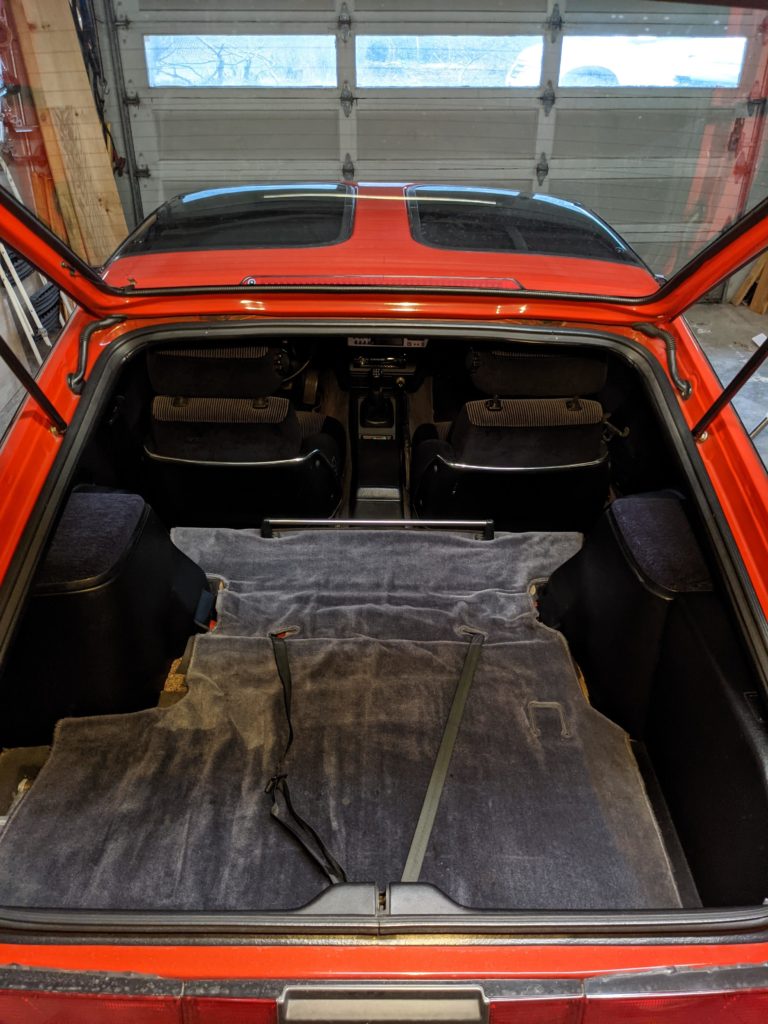
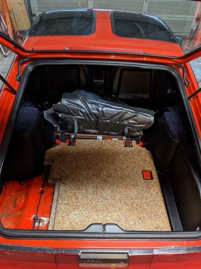
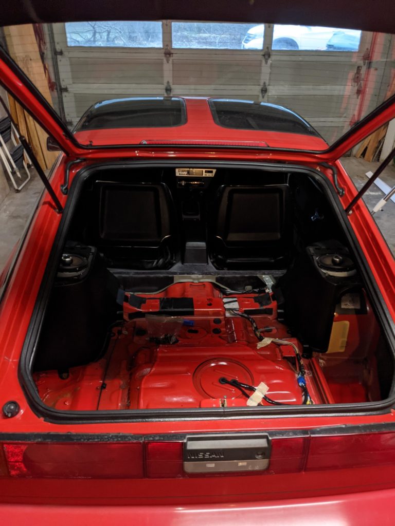
Interior Disassembly
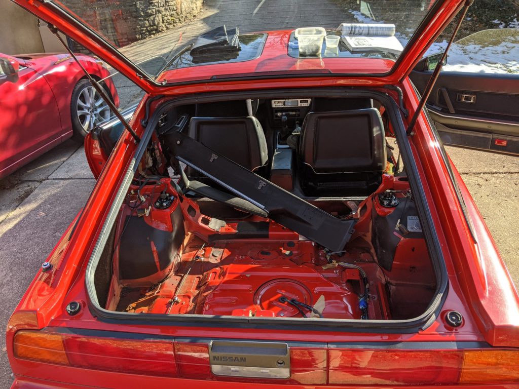
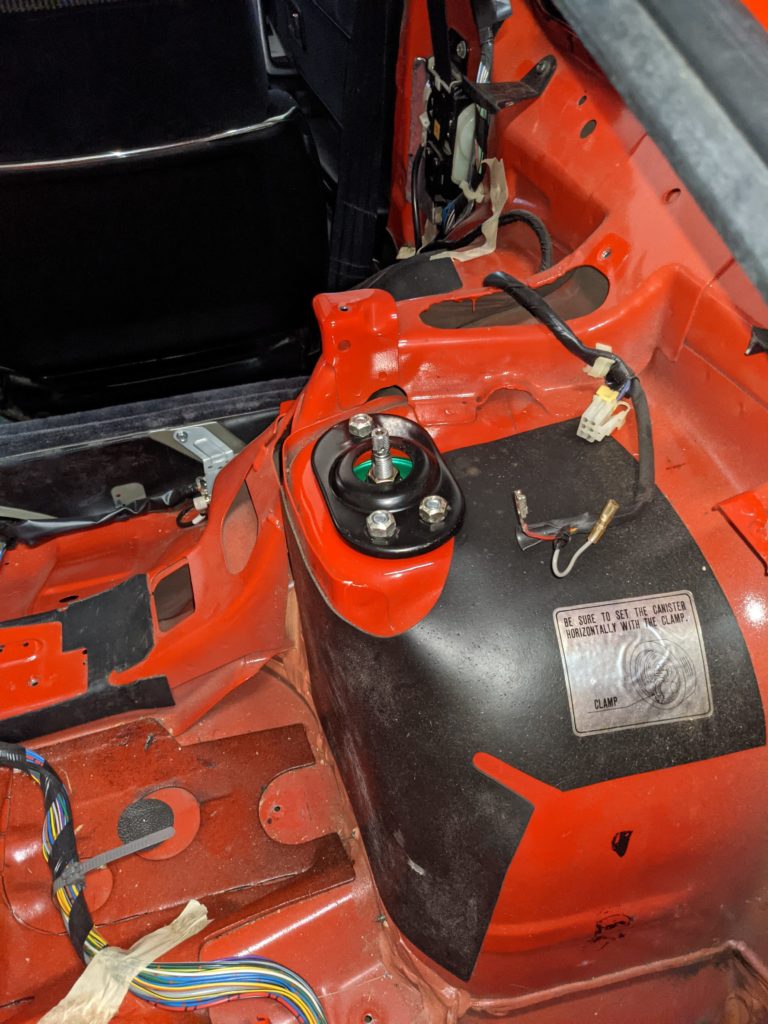
The first step is getting access to the strut towers. These are conveniently placed in such a location so you have to remove literally the entire hatch interior to get clear access. Despite what some tutorials say online, I suggest going through the process and actually removing everything instead of trying work around it.
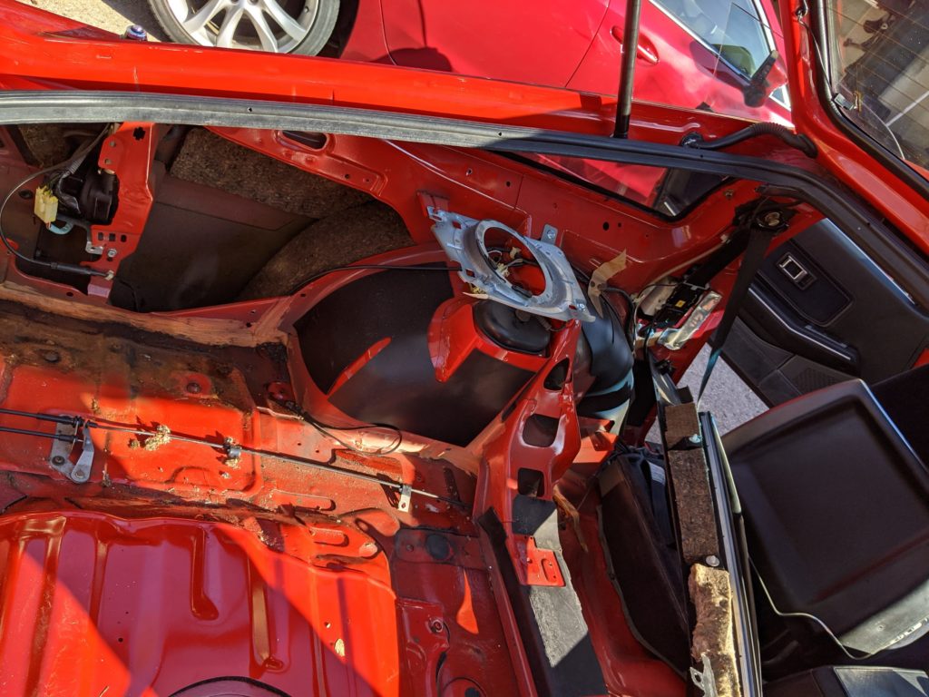
The primary challenging item with this disassembly are the two rear quarter window trims. After removing the carpet and all trim near the tail lights and spare tire, you should have decent access to the quarter window trim. After ensuring all fasteners are removed, it comes down to gripping the trim and pulling directly away from the body of the car. You will likely break off a few of the metal clips that hold the trim to the top of the car, but these can easily be remounted with some glue or JB weld. Once the quarter window trim is removed you are able to take out the plastic covering the strut towers

Exterior Disassembly
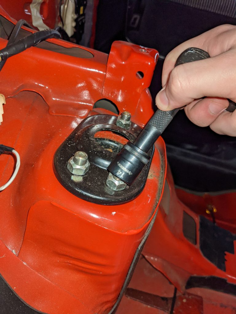
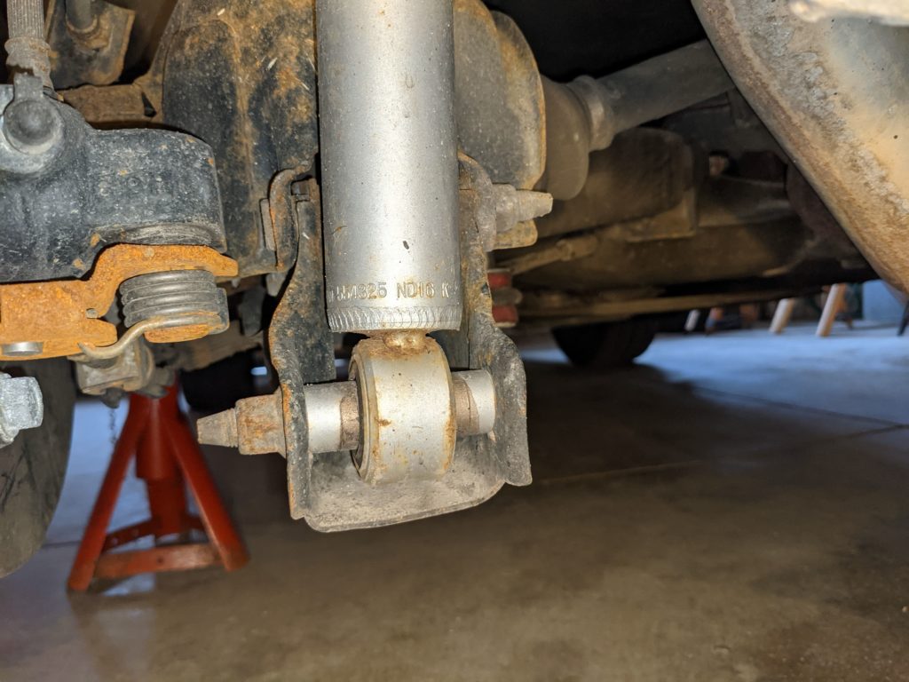
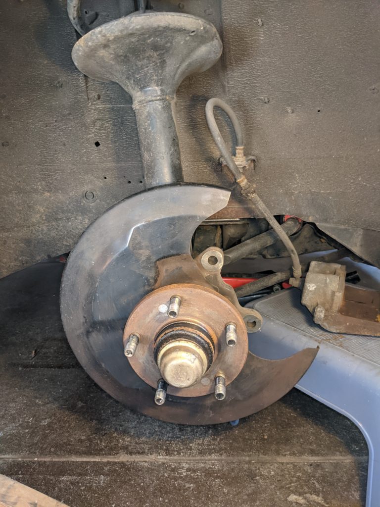
Jack up the control arm right underneath the shock absorber to relieve tension on the bolt that holds it in and keep the shock planted to the body of the car. Move inside the hatch and undo the 3 bolts that hold the top of the shock in. Save the reinforcement plate for later use. Move back to the wheel well and undo the long bolt holding the bottom of the shock in. Once removed, slowly drop the arm back down while holding on to the body of the shock. It should come out easily.
Removing the spring is a bit more of a headache. Borrow or buy a set of spring compressors. I do not suggest using the ones pictured as the body of the car gets in the way of the very long threaded rods. Compress the spring until it is able to clear both the top and bottom spring seats, at which point you should be able to remove it from the car. Be careful where you put your fingers as these springs can be very dangerous.
I took the time to brush off surface rust and coat the control arm in some rust converter. Once dried I covered the entire area with some new undercoating to hopefully reduce road noise and preserve the life of the metal.

Installation
Installation is basically the opposite of disassembly with a few small changes.
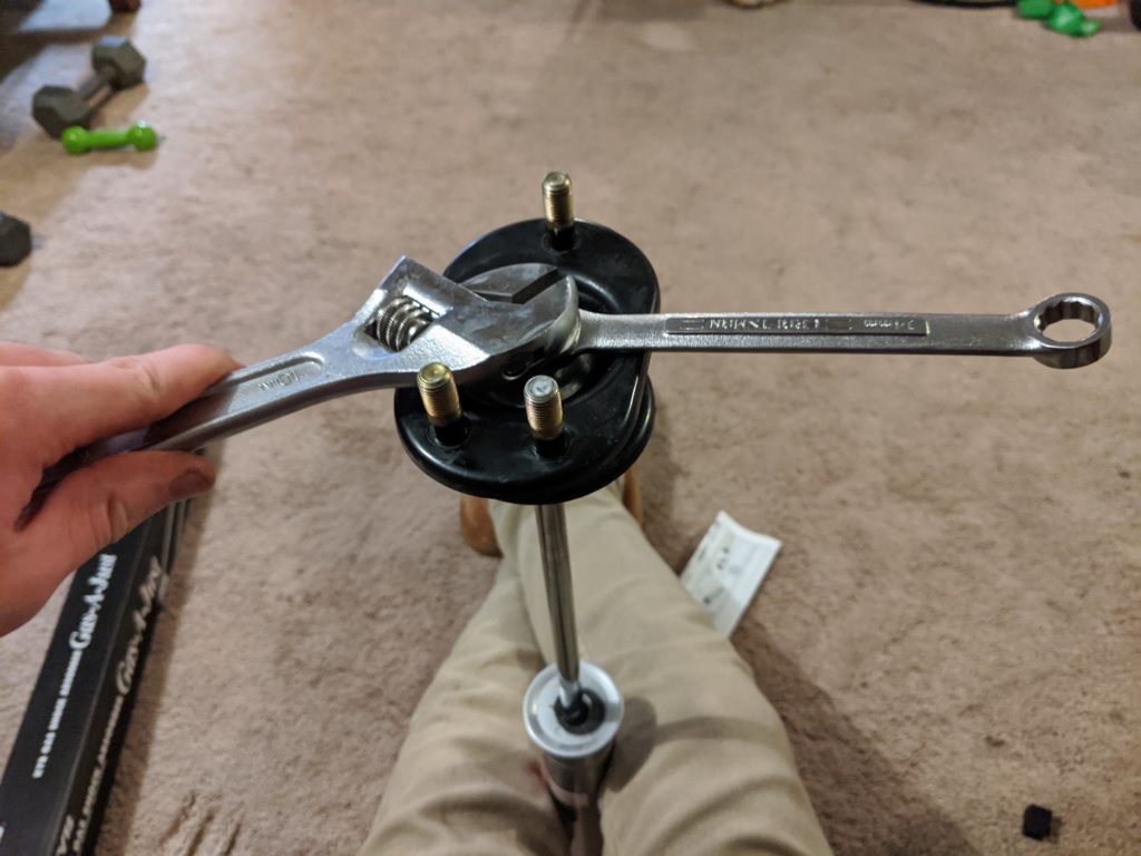
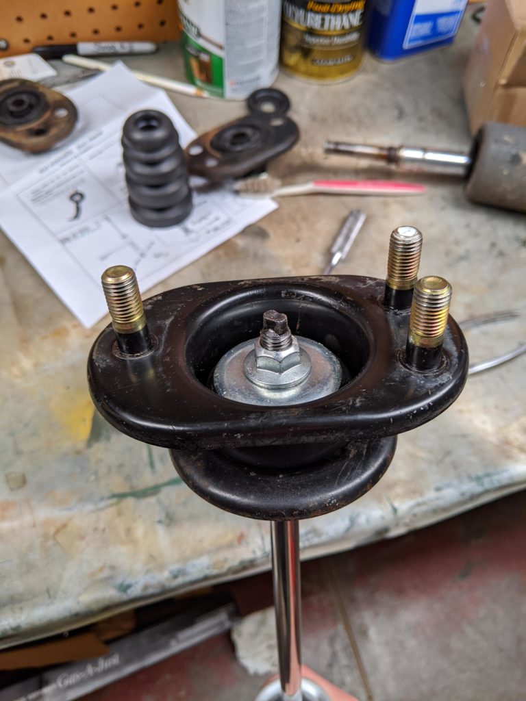
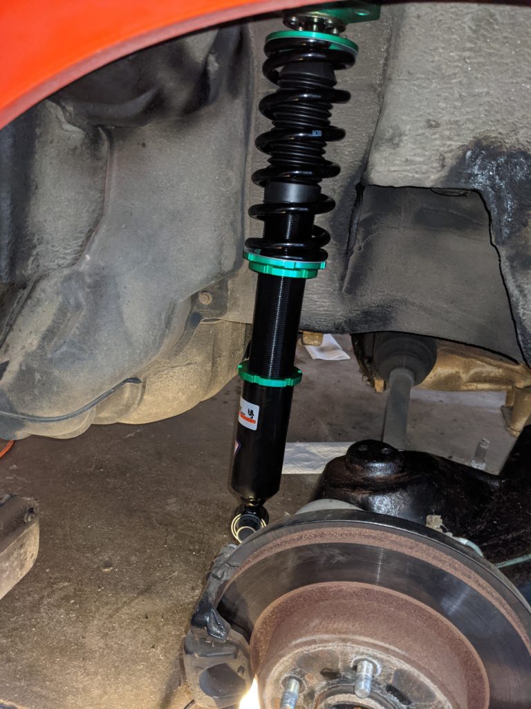
Using the reinforcement plate, loosely bolt the top of the coil to the car, leaving the coilover hanging. Rotate the coilover so that the long portion of the bolt sleeve is facing outwards and insert the provided brass-looking sleeve on both sides. Jack up the control arm and guide the coilover so that the bolt holes align. Once done, insert the bolt so that the head of the bolt faces the inside of the car and nut faces outwards. With the control arm jacked up, torque all fasteners to the values specified in the factory service manual.
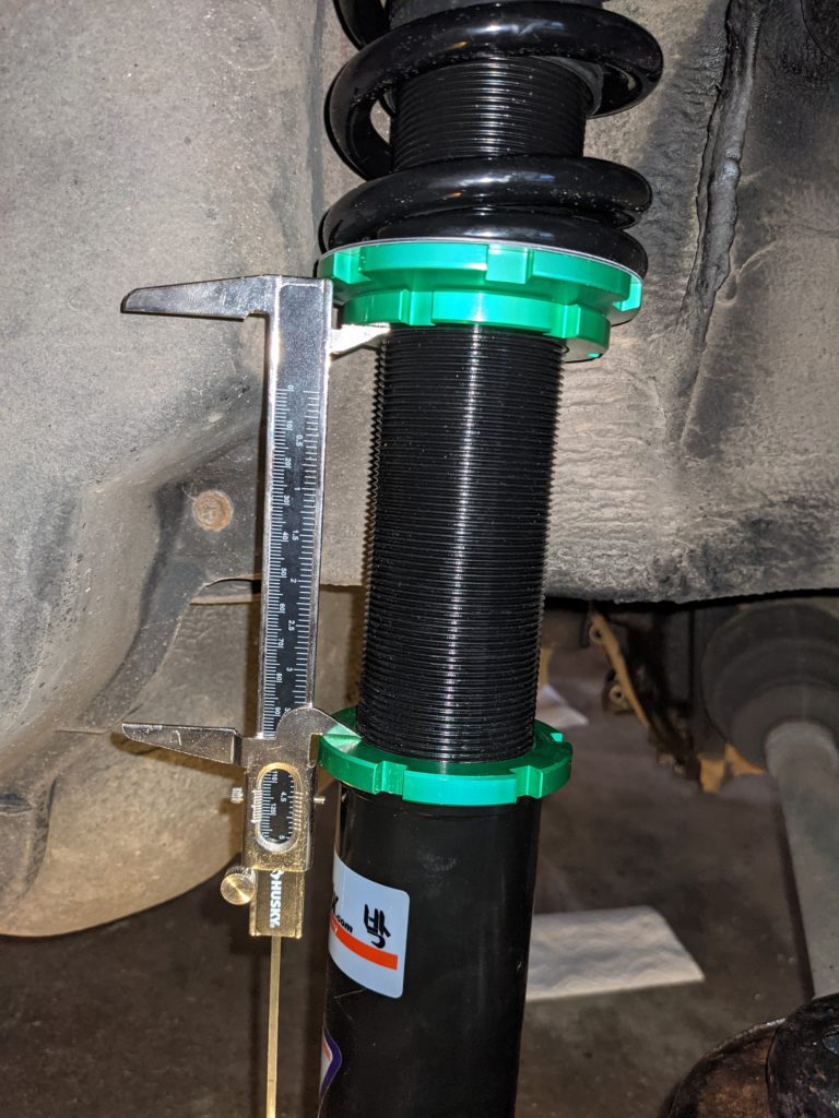
Once everything is tightened, it’s time to adjust the ride height of the coil. Powertrix specifies that the minimum number of threads needed for a secure fit between the shock and mounting cup is five (5). They also suggest that twelve (12) to fifteen (15) threads is equivalent to about a 1 inch drop in ride height from stock on most cars. I have since forgotten the exact number of threads I settled on, but I wanted to keep my ride height close to stock so I believe I landed somewhere between five and ten threads. Once you adjust the ride height and verify that both coils are set the same, tighten both sets of lock nuts with the provided spanner wrenches.
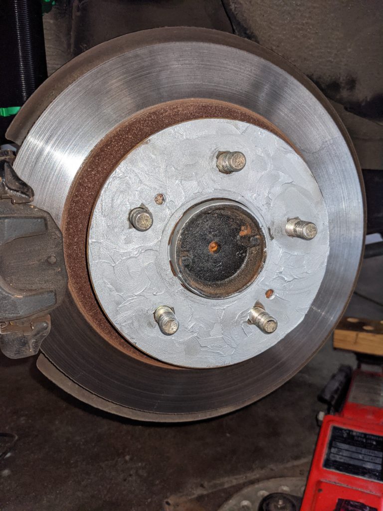
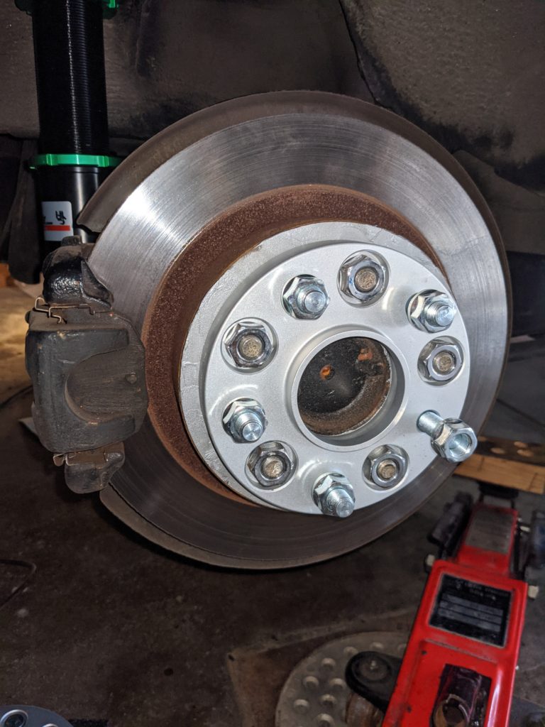
The final step is to put on the wheel spacer. I first used a wire brush to clean up the outer surface of my brake disk. I then put a healthy coating of anti-seize on to prevent the spacer from welding itself to the brake disk. The 20mm spacers are large enough that you do not need to shorten your lug studs. Using the OEM lug nuts, I tightened the wheel spacer to the same torque spec at the wheels. Applying the emergency/parking brake should be enough to let you torque them fully, but you can also insert a screwdriver in to the vanes on the brake disk to prevent it from rotating.

Front Installation
Disassembly
The front requires a bit more disassembly on the outside of the car but is much easier in my opinion since you don’t have to tear apart any of the interior.
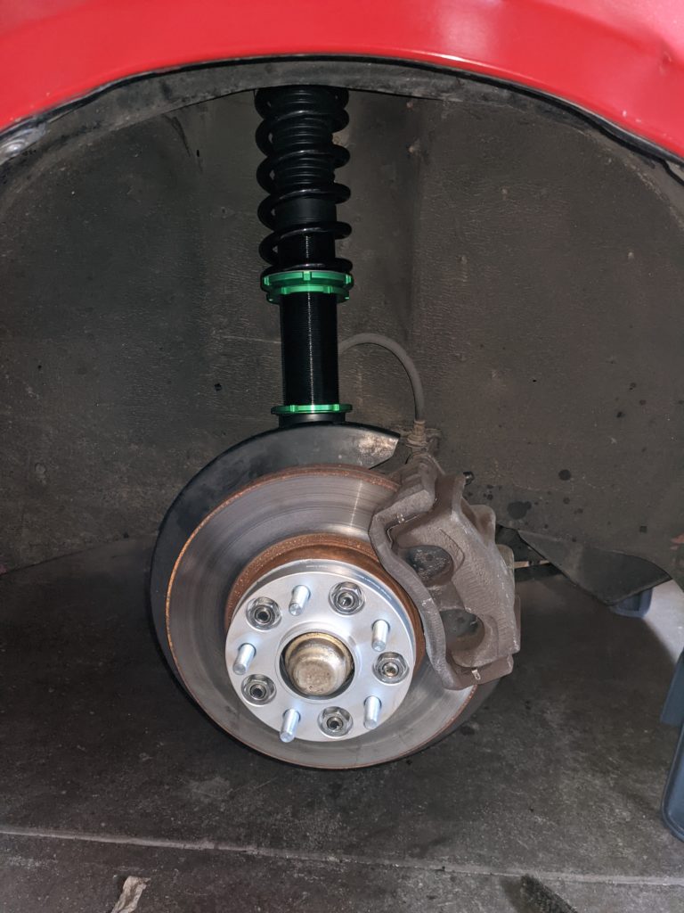
First remove the brake caliper and disk. Be sure to set the caliper on a platform as to not strain the brake line. Normally I would hang it from the spring, but we will be removing it so the platform is a necessity.
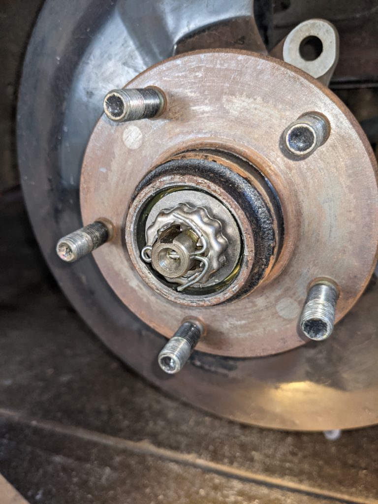
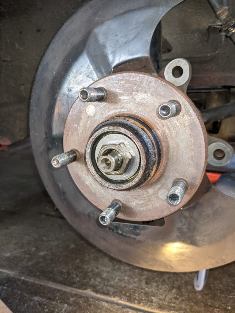
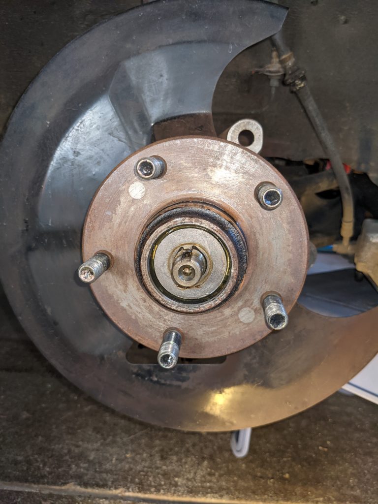
Once the brakes are out of the way, use pliers to take the center cap off, revealing the wheel bearing. Remove the pin, lock nut, nut, and hub in that order. I suggest keeping both the inner and outer wheel bearings within the hub as to prevent dirt from getting in. Place the hub somewhere clean and out of the way as well.
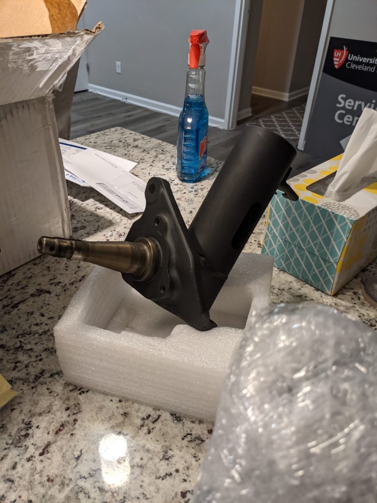
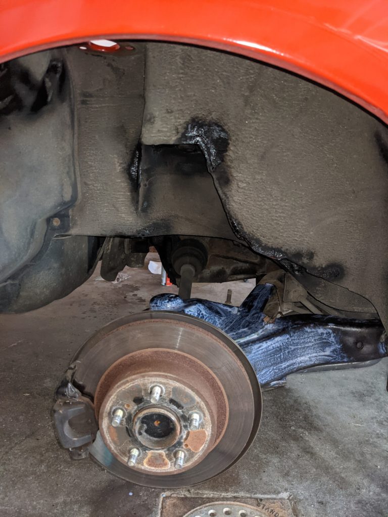
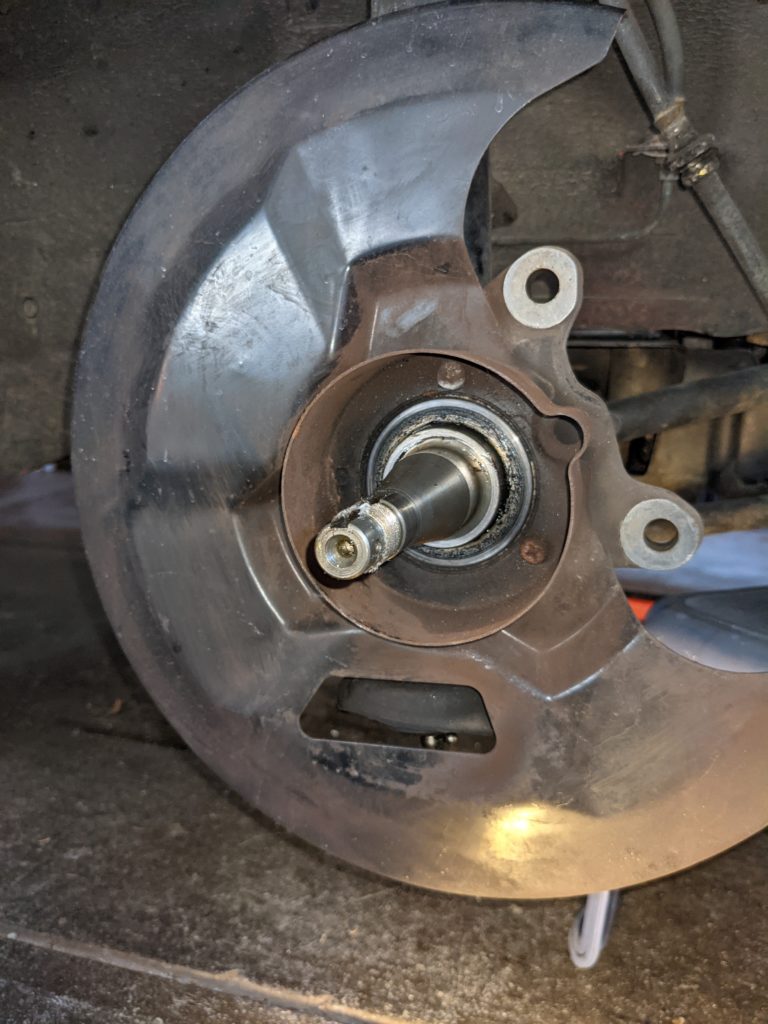
The dust shield comes off with three philips head screws. Be careful removing these as they are made with a very soft metal. Using the steering wheel, “steer” the knuckle so it is full lock in one direction and loosen one of the bolts on the bottom. Then rotate the wheel to full lock the other way and loosen the second bolt. Once both bolts are removed, the bottom of the strut is only held in with friction.
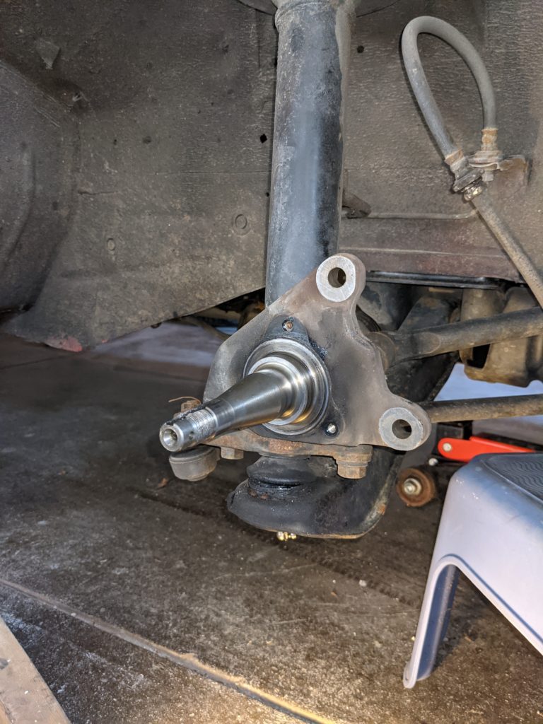
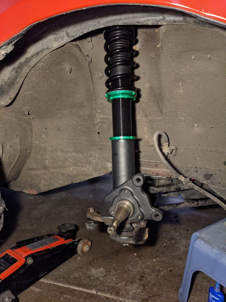
I suggest removing the bottom of the strut from the knuckle with the three top bolts in place so that it doesn’t fall violently when it comes loose. Stepping on the control arm was enough to free the strut in my case. Once free, you can remove the top three nuts and remove the strut and spindle assembly in its entirety.
Make sure to clean up the area. My struts must have rusted a hole in the bottom a lot of rusty oil came spilling out of one of them. A wire brush and rust converter goes a long way in preserving these parts.


Installation
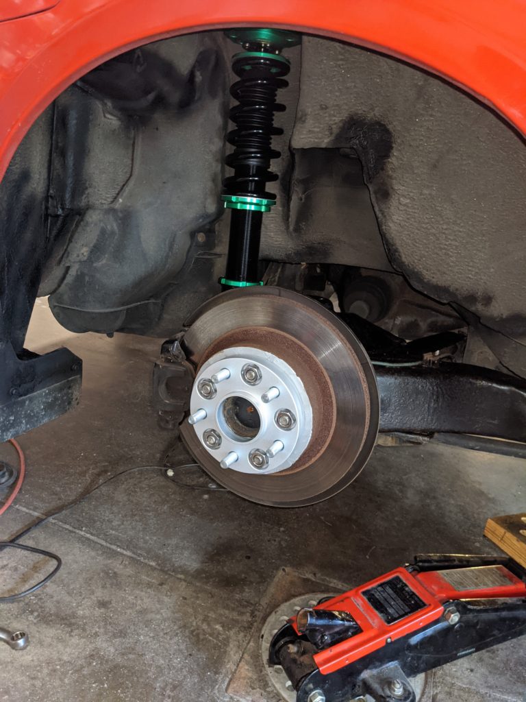
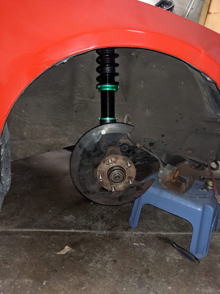
IMPORTANT NOTE: The spindles are not interchangeable. Please note that the caliper bolt holes MUST be facing towards the front of the vehicle. Pictured here is the passenger front wheel well. The spindle will be mirrored on the other side. It is also very important to ensure that the top of the coilover is rotated correctly. The mount is asymmetrical so it should fit only one way, but ensure that the camber adjustment is aligned such that the coilover can tilt towards and away from the body of the car. It is camber and not caster adjustment after all.
I recommend getting the coilovers close to the same ride height outside of the car before putting them in. The same rules apply when it comes to the necessary number of threads.
Before installing, move the four bolts used to adjust camber to the innermost holes, as they could interfere with the access hole on the top of the strut tower. Once you dial in your desired amount of camber feel free to move them to the widest accessible holes.
Before putting the wheel hub back on, make sure to grease up the spindle with some wheel bearing grease.
I also suggest zip-tying the dampening adjustment knob to the body of the coilover to prevent it from banging around when driving. Don’t forget to install the wheel spacers here too.
After tightening all bolts to spec, and verifying that both coils are set to the same height, you can put the wheels on and take a lap around the neighborhood to let the suspension move around and make sure things are settled. You may need to jack the car up and adjust the front/back height a few times to get it right.
Enjoy your new suspension!