Valve Hummingbird Clone
Re-using Index speakers to mimic the headphones shown in Valve’s ear speakers documentation
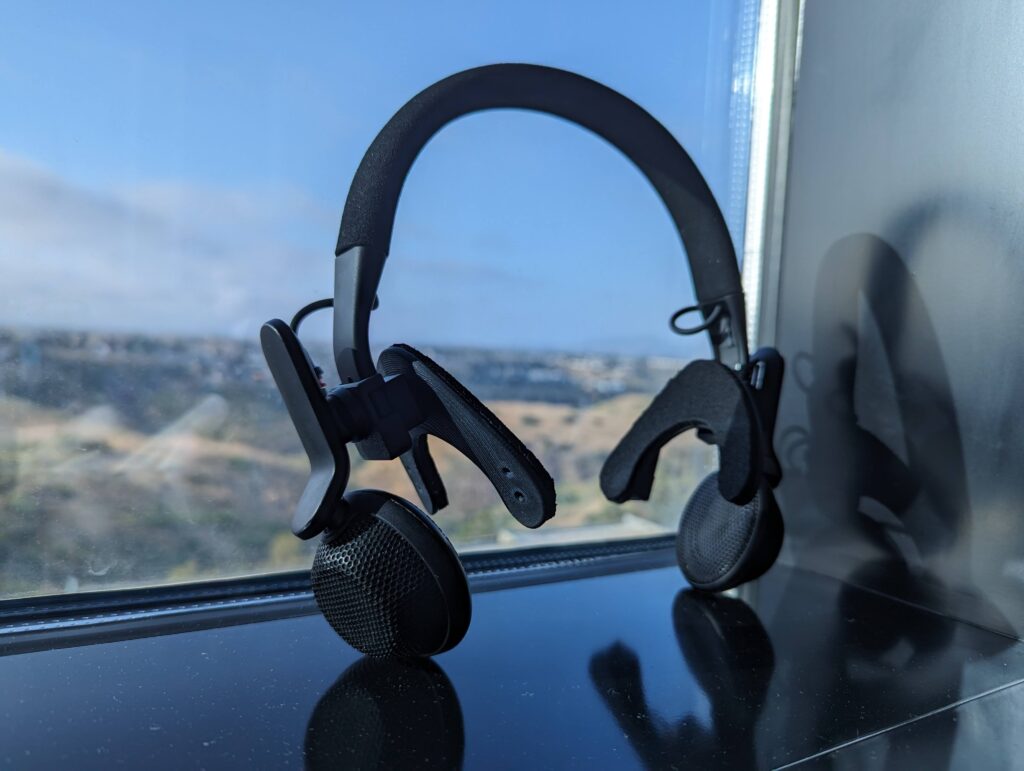
Mechanical Design
Choosing a headband
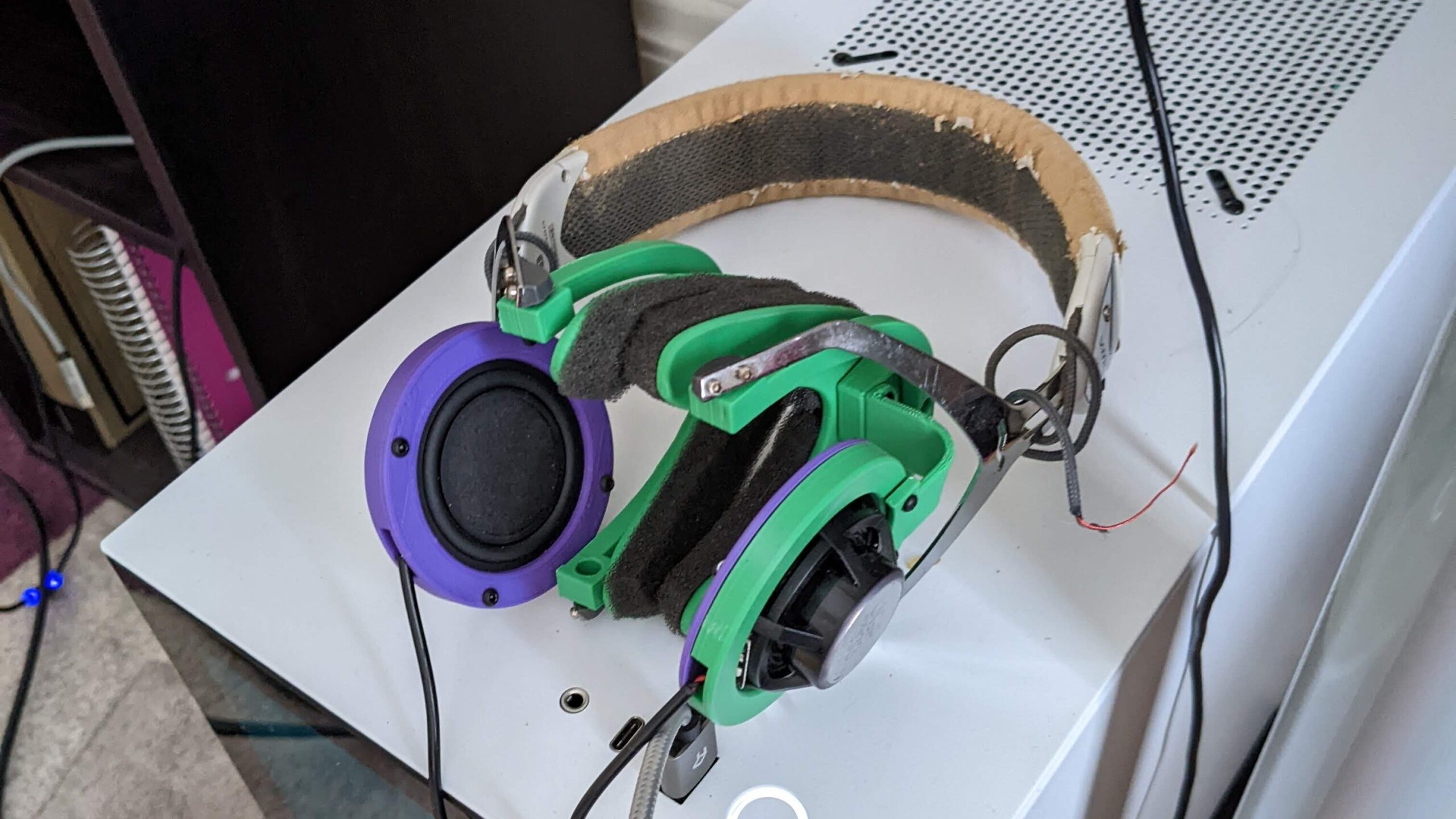
I attempted this exact project ~3 years ago and struggled with the ergonomics of the head band. I used an old V-Moda headband for initial prototypes, but did not enjoy the crustiness.
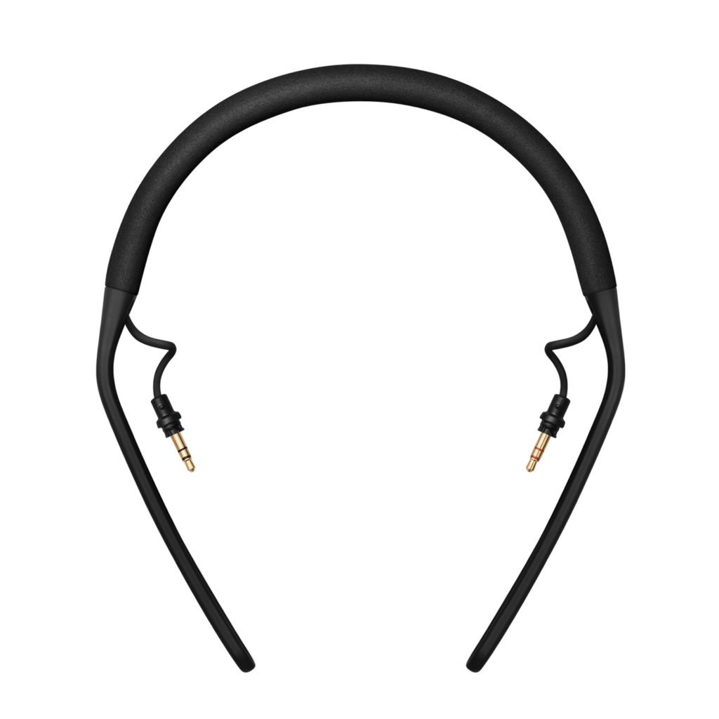
The AIAIAI headbands are readily available and very simple. Unfortunately the nature of their adjustment mechanism means this project requires PERMANENT modifications. It’s worth it though, I think they fit the aesthetic very well and I appreciate the inclusion of 3.5mm plugs for easy integration.
Interfacing with the User
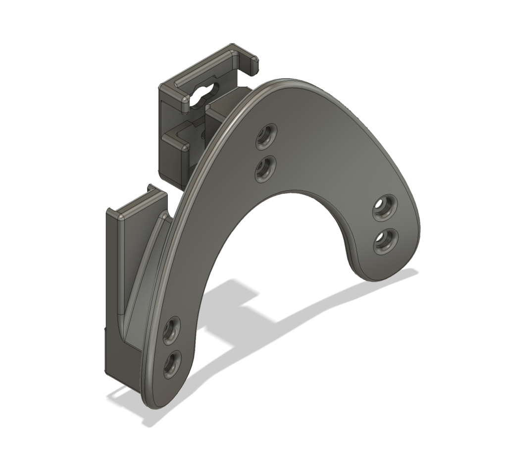
Thanks to the simple construction of the AIAIAI headband I could use a consistent 8mm hole spacing to mount the “wishbone” earcups to any OEM setting, though I did have to drill additional holes higher up on the headband to get things to sit right on my head.
I recycled the 8mm hole spacing to create a mount for the DAC. This can be mounted to either side of the wishbone to support cable entry on the left or right ear.
There is a small interposer block between the wishbone and headband which gives ~10mm extra spacing.
The outer-most component contains a housing for the BMR breakout board & constrains both the BMR rotation mechanism & the headband. Looks clean too 🙂
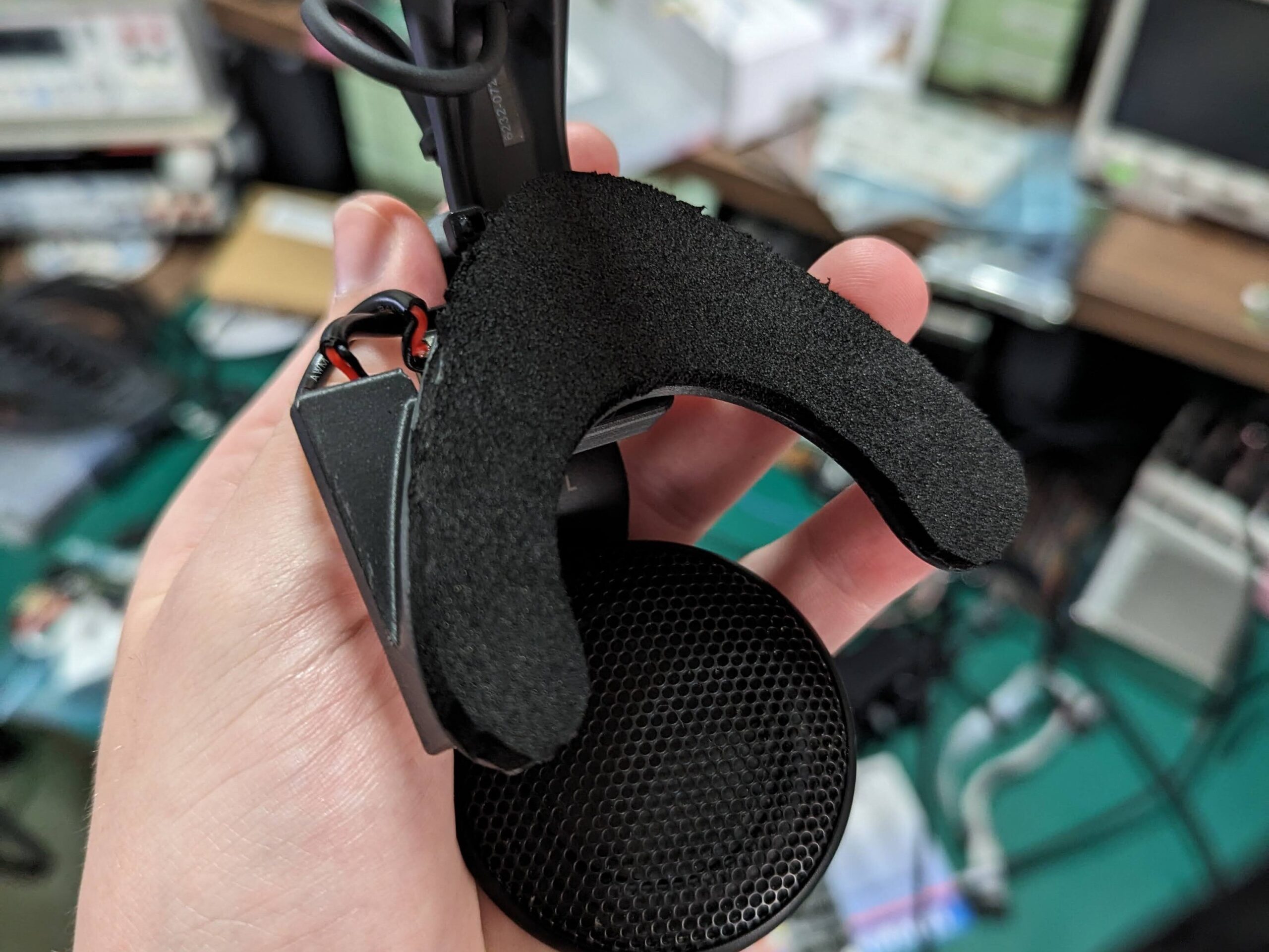
I added some EVA foam to the wishbones for a little extra comfort.
The foam is affixed with standard super glue. Honestly it’s a bit too firm for my tastes, but it does help a bit with pressure points.
If you have any suggestions for better foam types please get in contact.
Electrical Design
This project is powered by Sctanf’s Picoamp. I redid the layout to incorporate a few key features, but essentially the design is unchanged. For the time being there are no changes to the EQ that Sctanf baked in to the firmware. These parts are all bespoke but I will share any spares that I have, just get in contact 🙂 (info at the bottom of the page)
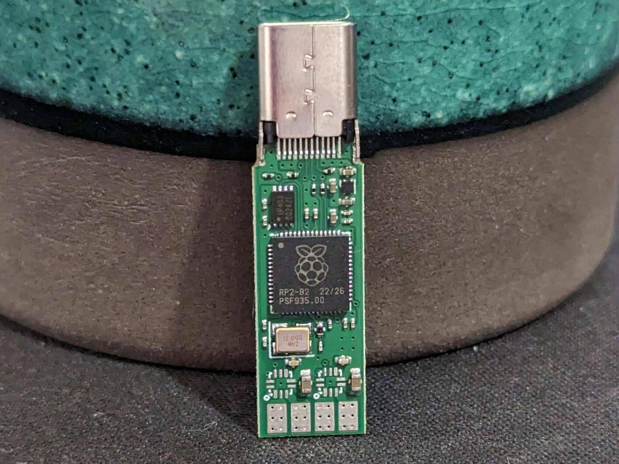
The DAC/Amp
This modified version of the features the following:
- Female straddle-mount USB-C connector
- RP2040 uC
- 2x MAX MAX98360A I2S Class-D Amplifiers
- 4 big ol solder pads
Originally the design was intended to have a male connector but I oopsied and selected the wrong one. WHOOPS! Works better for this project anyways.
I completely redid the layout to incorporate 4 layers because time is money & I am a sucker for good power distribution, even if it is unnecessary.
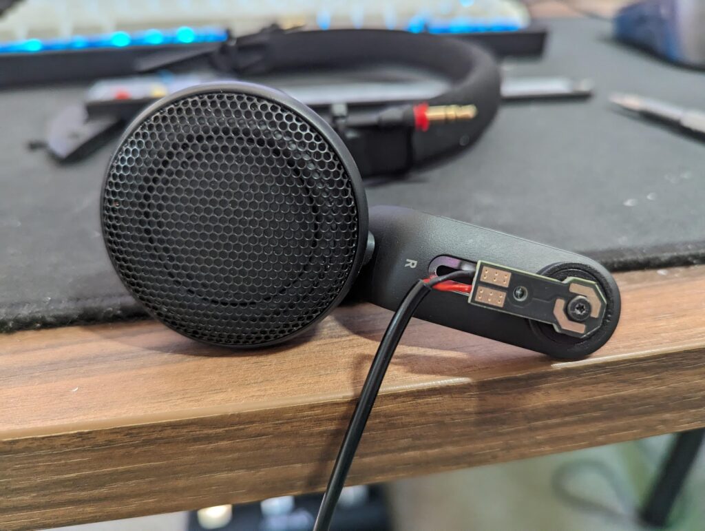
BMR Connection
I’ve seen a lot of janky ways to interface with the Index BMRs. If you look inside your index strap you’ll see a few copper pads that interface with the pogo pins on the speaker assembly. So I decided to mimic that!
These breakout boards are extremely simple, just a couple solder pads & corresponding pogo pads. The pogo pad shape is designed specifically to allow the solder pads to point in all 4 cardinal directions w.r.t. the arm of the speaker in neutral position. The reversible design allows you to swap polarity without having to re-solder, though admittedly that feature is unnecessary.
I gold plated these boards because it looks cool, but also something something good non-corroding surface finish or whatever.
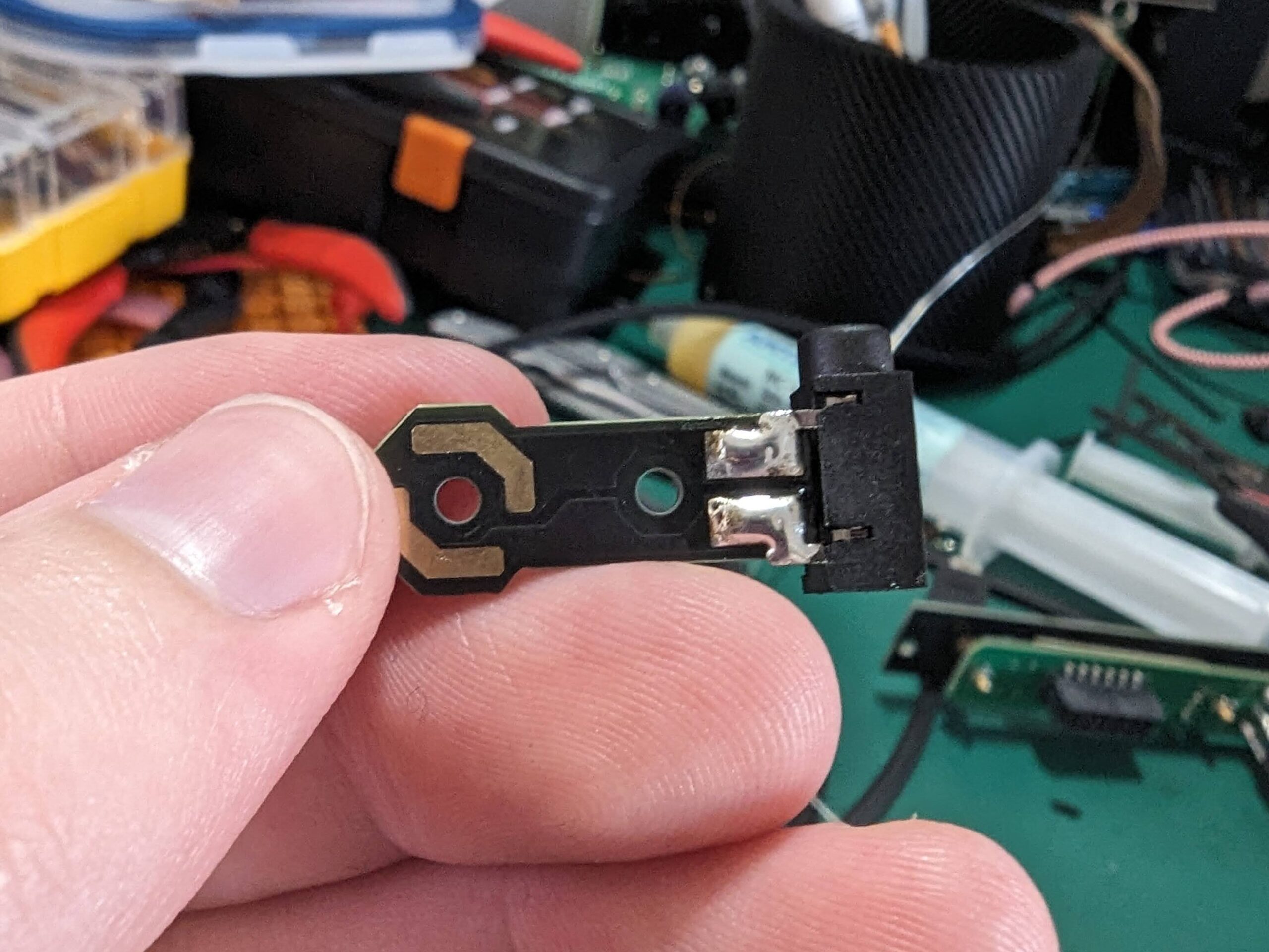
Crossover Connection
The AIAIAI head straps include 3.5mm TRS plugs on either side of the headband.
Conveniently i had some 3.5mm jacks which just barely fit the solder pads on the breakout boards mentioned above.
In this configuration the tip is ‘hot’ and the sleeve is ‘cold’. This choice is arbitrary, but seemed to produce good results so I haven’t bothered swapping it back.
Future Plans
I’m not entirely satisfied with the product as it stands. I still have one zip-tie and that is just UNACCEPTABLE!!!! I would also like to enable people who do not have access to any soldering equipment to build this project, so I’ve redesigned everything. Just waiting on parts to arrive at the manufacturer 🙂
DAC/Amp Redesign
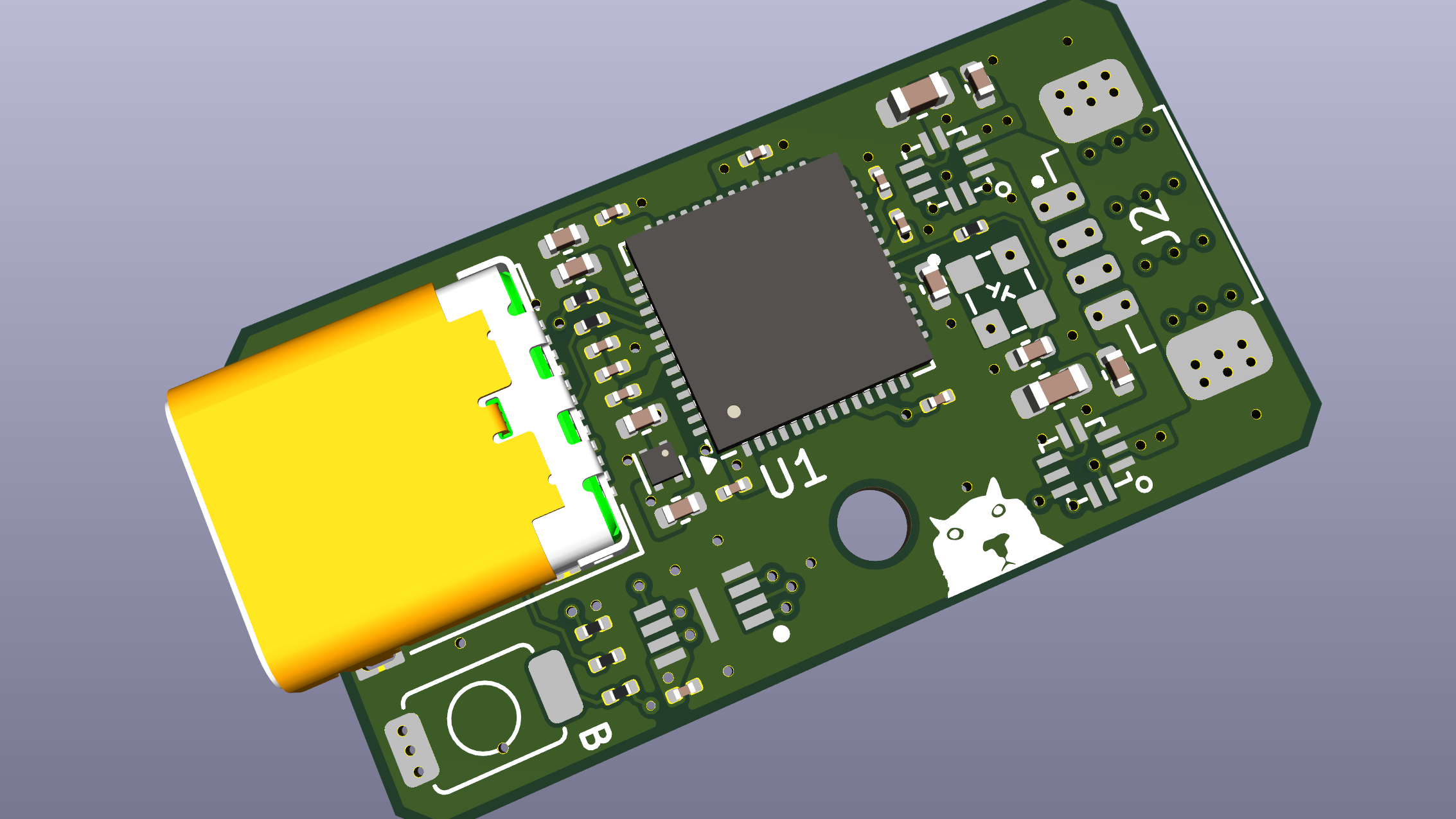
While I loved how slick the straddle-mount USB-C connector was, it just doesn’t make sense from a manufacturing cost standpoint. I have replaced it with a more standard USB-C connector 🙂
Previously to re-flash the RP2040 you had to precariously short two pads while simultaneously plugging the USB cable in. Didn’t work too well, so now there’s a convenient little switch to hold down!
To allow solder-less use I included a Molex Picoblade 1x4p connector. This is a SUPER common connector so you can buy off-the-shelf wiring assemblies or even pin your own out!
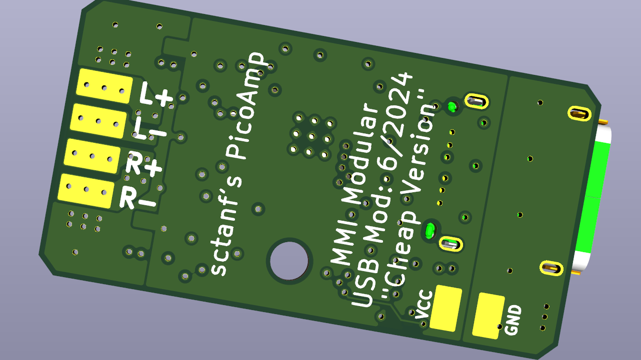
The back side has some features too!
I retained the big ol’ solder pads for the amplifier outputs for anyone who still wants to manually wire things in.
I also included VCC & GND plane connections for external power injection. The purpose of this is for power-limited applications such as use with the Bigscreen Beyond HMD.
BMR Interface Redesign
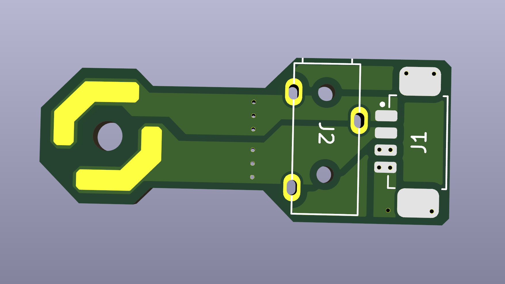
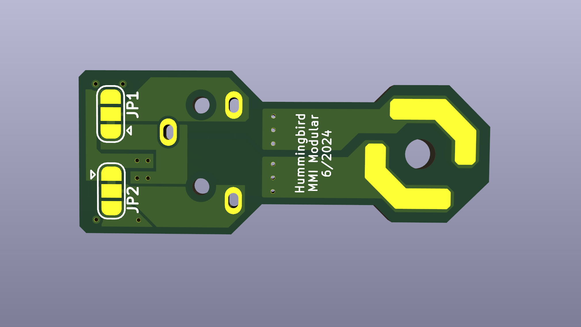
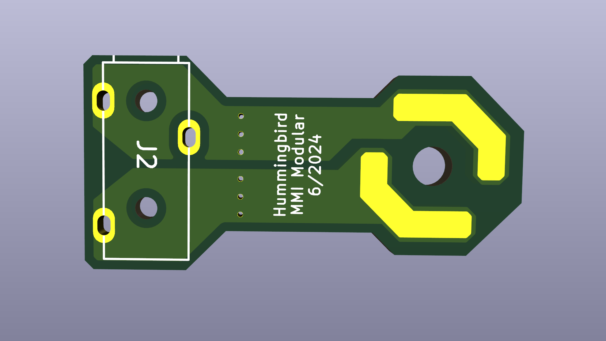
To support solder-less users, I integrated the aforementioned Picoblade connector on one version of the BMR breakout. This version includes a 3.5mm jack to support the headband cross-over cable. The backside of the adapter has solder jumpers to cover my ass in case I got the polarity wrong.
This design looks vaguely phallic… my bad…
The Project is Done!
I’ve completed all the ‘future work’ described above. The new picoamp DACs were a harrowing experience. After ordering 50 of them, I only had 1 or 2 which worked at room temperature. It turns out that the flash memory I obtained from JLCPCB was marginally compliant with it’s maximum clock spec & the overclock applied by Sctanf marginally exceeded that spec.
If you’d like to read more about the debug (which I found very interesting), you can read more here
Improvements
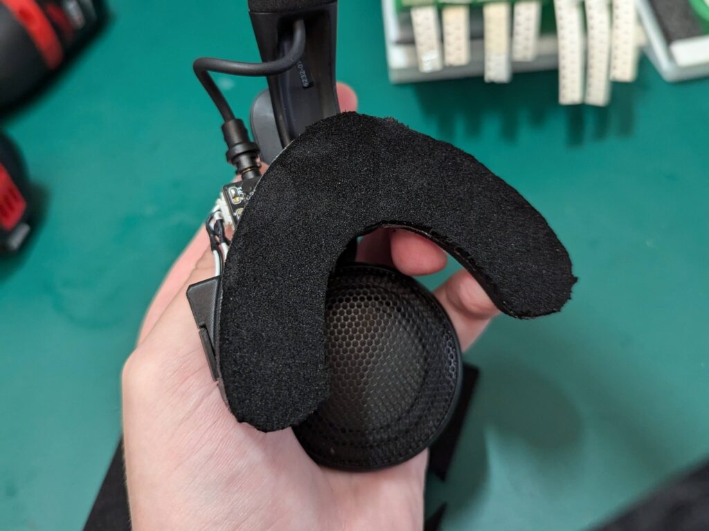
There’s been a few changes to the design to make things a bit nicer. First off, I increased the surface area & decreased the curvature of the wish bone to improve comfort.

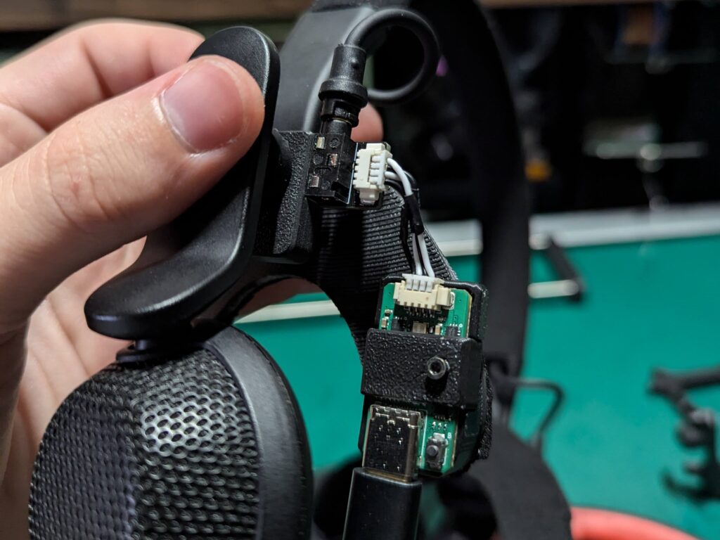
Second, everything is now “plug & play” No more soldering!!! Woohoo!!
Sctanf has been a trooper and added a few sick features to the picoamp firmware:
- Boot button is multi-function
- Short press -> restart RP2040 – helps in case of bad USB connection
- Long press -> enter bootloader – makes swapping firmware/eq quick & easy
- Refined EQ
- Version 3.x is tuned according to a measurement directly at index BMR pins
- Version 5.x is tuned according to a measurement taken by a microphone near the BMR
- Better bass ducking to prevent clipping
- Reduced 64-bit math to 32-bit math
- Allows for ~16 biquad filters to run
- Less overclocking needed with provided filters
Everything you need to make your own!
Assembly Guide
3D Files
Electronics
The DAC -> BMR connection is pinned out for this wiring harness. I decided to make my own so that it could be minimum length. If you’re interested in custom-made wiring assemblies that are the right length please let me know 🙂
If you have any questions feel free to reach out via email: mmimodular@gmail.com or discord: matt_owo