Laser Tracking Servo
This device was created for my practical circuit design class at Case Western. Special acknowledgement to my lab partner JC for helping with all these designs.
Specifications
What we are provided
- DC servo with slip clutch to prevent damage.
- Mounted to motor:
- 5V DC laser diode unit
- 300° potentiometer
- 2-3/8″ square photovoltaic (PV) cell mounted to a wooden block.
- Single 15V power supply.
What we must accomplish
- Design a circuit with two buttons to manually move the servo clockwise and counterclockwise.
- If no button is pressed the servo will automatically find the exact center (0.1″ tolerance) of the PV cell.
- If the laser is not incident on the PV cell, the motor will rotate to locate the cell again.
- The PV cell must be 6 feet or further from the laser.
- Bang-bang control is strictly prohibited.
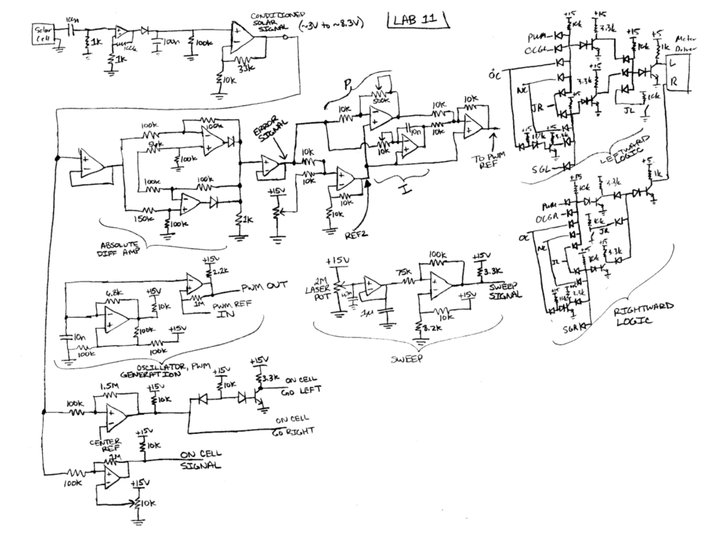
Complete Schematic
Pictured below is the complete schematic for our control circuitry. I will break it up in to sections to better explain each function in a bit more detail.

Motor Direction Logic
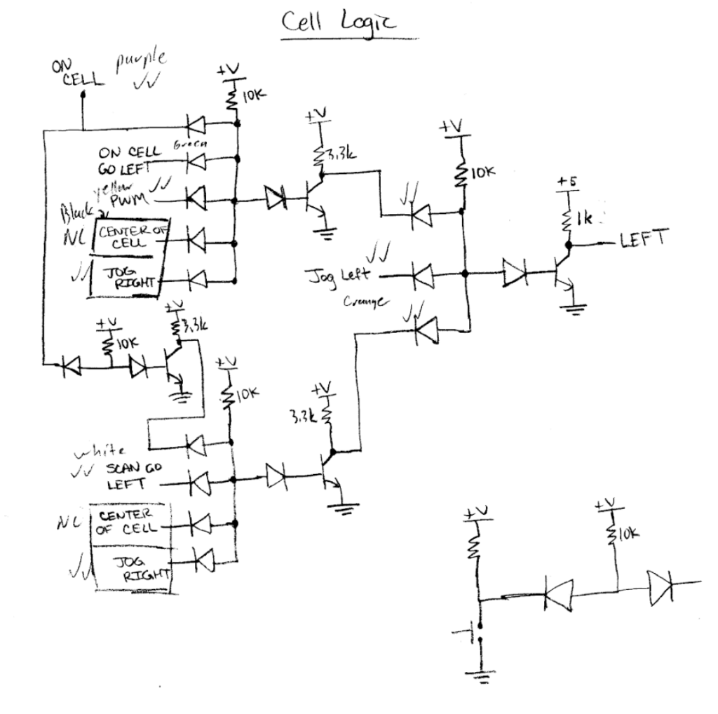
This is the primary brains of the motor control. This takes in every variable necessary to determine the proper way to run the motor and PWMs the motor to turn in the proper direction. This logic is repeated to accomplish clockwise and counterclockwise rotation independently.

We opted to use DTL (diode-transistor logic) for this application because we discovered that much of our logic boiled down to one NAND gate with many inputs. We did not have any specialized CMOS logic ICs in the lab that accommodate more than two inputs so this was the next best option in terms of circuit simplicity. Unfortunately we failed to realize that our motor driving IC had a pin specifically for PWM, which could have simplified this a little bit.
The signals we felt we needed to get the system running were as follows:
- On Cell
- Indicates when the laser is present on the PV cell at all.
- Center of Cell
- Indicates when the laser is near the middle of the PV cell within a certain window.
- On Cell Go Right
- Indicates when the laser is on the left side of the PV cell.
- On Cell Go Left
- Indicates when the laser is on the right side of the PV cell.
- Scan Go Right
- Indicates when the laser is not present on the cell and the motor should rotate clockwise.
- Scan Go Left
- Indicates when the laser is not present on the cell and the motor should rotate counterclockwise.
- Jog Right
- Forces the motor to rotate clockwise.
- Jog Left
- Forces the motor to rotate counterclockwise.
Detection & Control
The very first thing we did was use an overhead transparency sheet to print a gradient which we could tape over the solar cell. This would give us a different voltage depending on where the laser was located on the PV cell since the ink would block more light on one side of the cell than the other.

After establishing a way to differentiate the left and right side of the panel we decided to tackle signal conditioning. Since our cell is photovoltaic, it is also susceptible to sunlight. Since sunlight is relatively constant, we decided that pulsing the laser was a good option for isolating the light from the laser itself. We used a highpass filter with a cutoff around 1.5 kHz to remove any DC from the incoming signal, then amplified it quite a bit. We turned this incoming signal in to a DC control voltage with a basic peak detector and amplified it a little more.
To be continued…