SteamVR Finger Tracking Glove
This project is in progress and will see many iterations as time goes on. Lots of it is new territory for me so progress may be slow.
Project Goals
The objective with this project is to create a standalone SteamVR controller that is integrated directly in to a glove. An optical sensor constellation will be placed on the back of the hand to capture hand position and wrist movements while other sensors will be placed on each finger to track the bend and splay of each finger individually.
DOI: 10.3390/s17040770
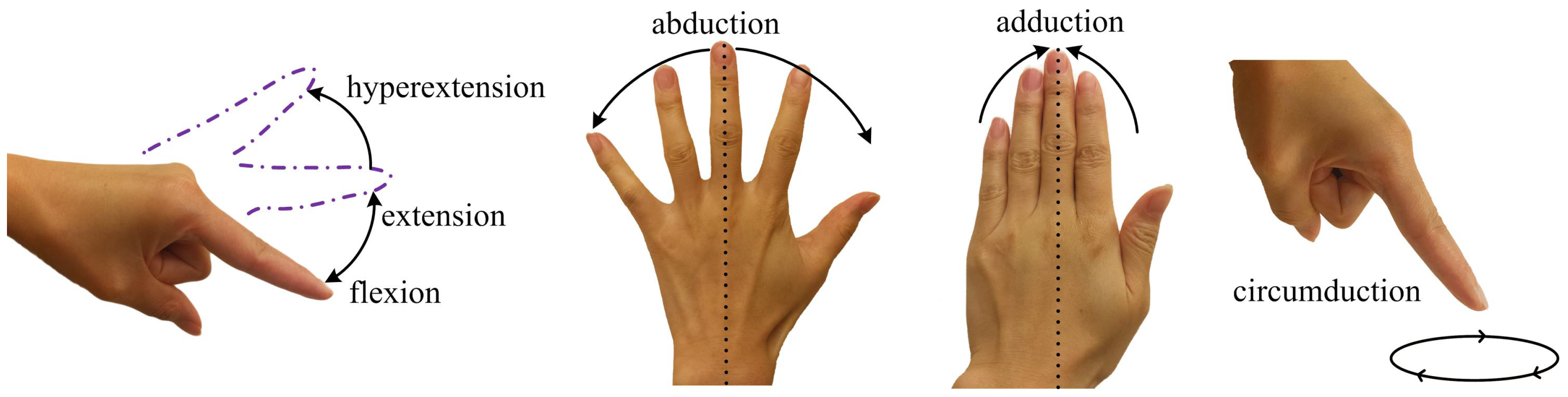
For this project I am not concerned with detecting hyperextension of the finger, though it may be possible with some sensing methods I am considering. The primary challenge will be sensing abduction and adduction in a way that is relatively unaffected by flexion of each finger individually. Proximity sensing methods would fall apart in cases where all but one finger are forming a fist.
The perfect sensor for this project is available directly from Bend Labs. Their two-axis differential capacitance sensor is stretchy, path independent, and highly accurate with stellar repeatability. The I2C interface used is also very convenient. Unfortunately I am unable to go this route due to the sheer cost of each sensor, coming out to a grand total of $1290 for the 10 sensors required for two complete gloves. As a result I am exploring other less accurate but far cheaper alternatives.
Sensor Selection
Flexion
Sensing the bend of a finger is nothing new, there are commercial implementations as far back as the classic Nintendo power glove. For this project I have found three potential candidates that are cheap enough for me to consider using.
Bend Sensor
This is the basic sensor used in a lot of VR glove implementations, and for good reason. They are (relatively) cheap at around $10 per sensor and offer pretty decent accuracy and response time.
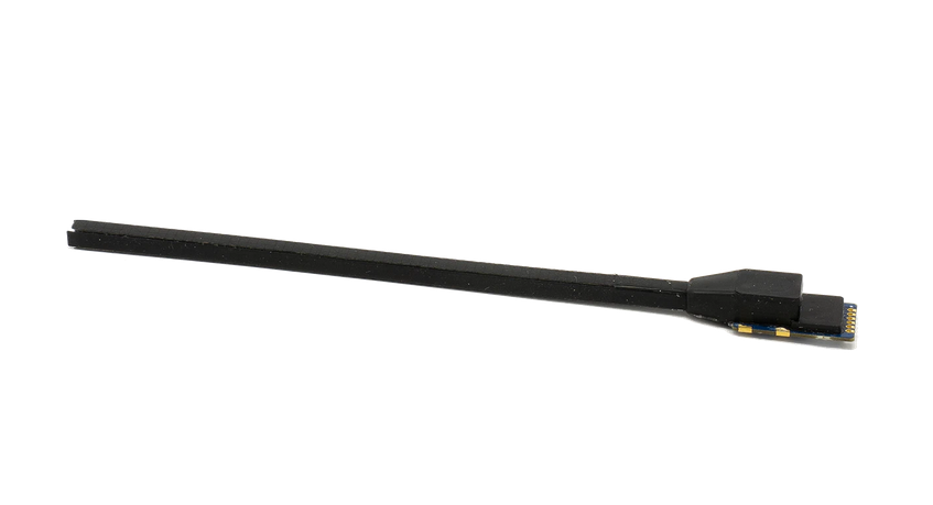
This 100mm flex sensor was purchased from Adafruit. It’s resistance when completely flat is around 10 kΩ and it increases somewhat linearly to 20 kΩ when bent around the outside of my fingers.
The primary downfall of this sensor is that it is rigid and unable to stretch. It is also rather fragile at the connector end so it requires some level of strain relief in order for it to stay operational for an extended period of time.
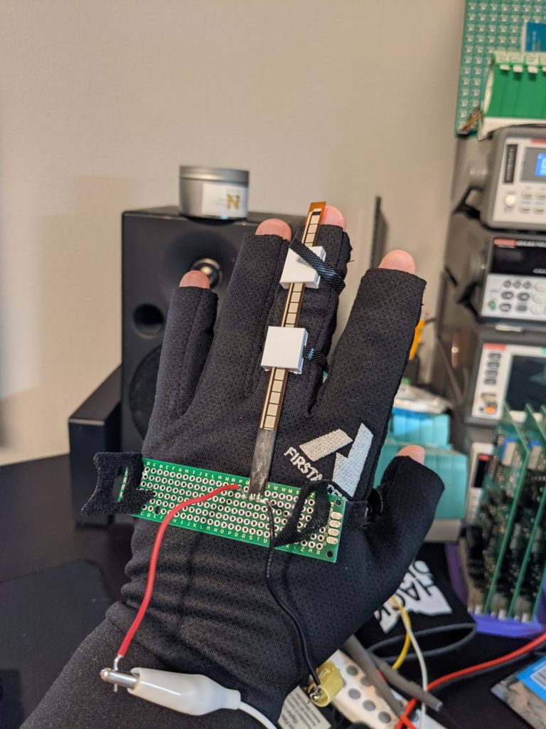
To get the sensor to bend around the outside of my finger I printed some rails in PLA that held the sensor in place while allowing it to slide with little friction. This isn’t ideal as I have a feeling it will wear down the sensor over time.
Conductive Rubber Cord
Found on Adafruit, this conductive rubber cord changes its resistance when stretched. It has a base impedance of around 350 Ω/in. I decided to try this out as a sensor since it can deform to fit the outside of the finger instead of needing the slide inside of a plastic guide.
I printed a set of guides in PLA that created a U-shaped loop of the rubber cord, doubling the effective length of the sensor and allowing all connections to be made at the first knuckle instead of having to run wires out to the end of the finger.
Initial testing showed a base resistance of around 3 kΩ with an increase to around 4.5 kΩ when fully stretched. Unfortunately the response to these changes were slow and had significant overshoot and recovery times. That coupled with the physical resistance to curling your finger caused by stretching the cord makes this non-ideal.
It would be a wonderful way to train grip strength though!
Hall Effect
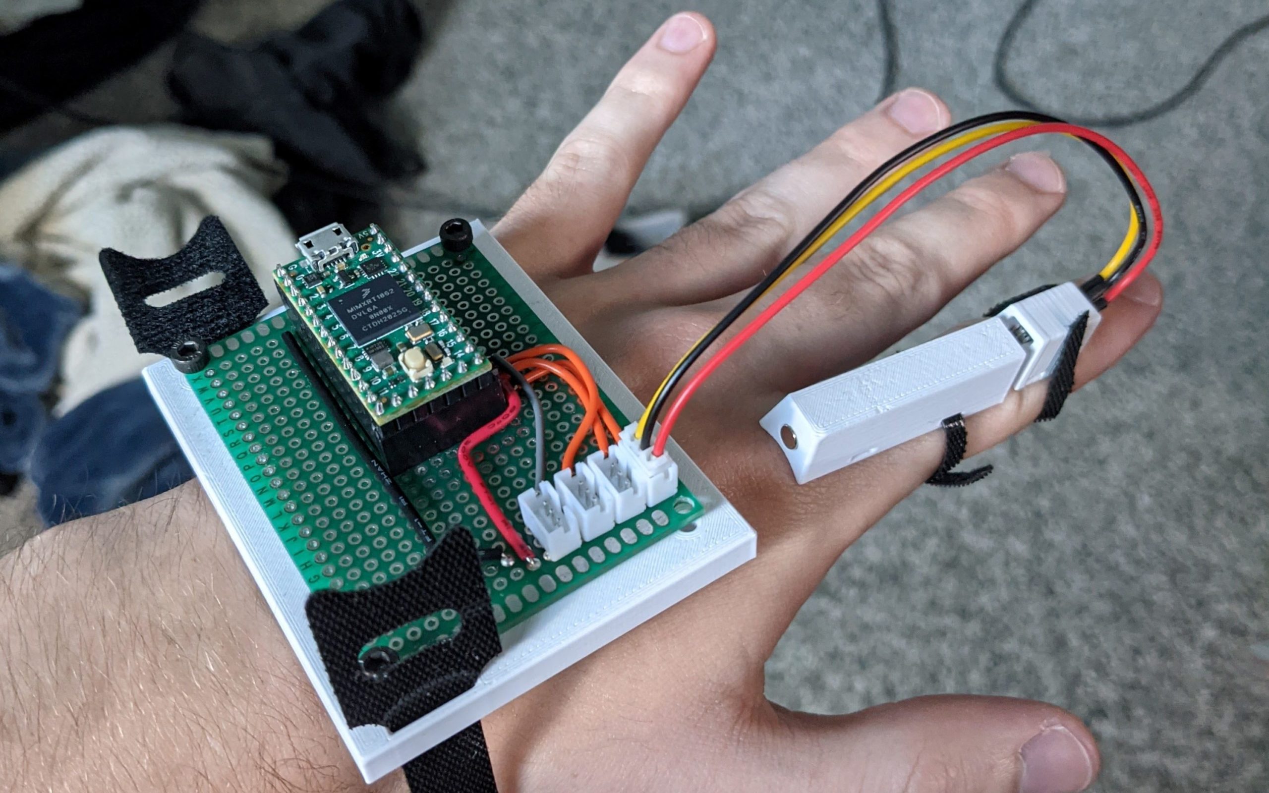
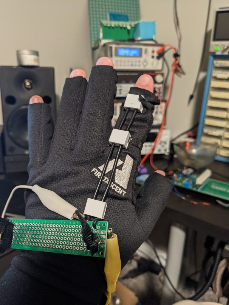
For the time being, I have settled on a pair of linear hall effect sensors on each finger. I have opted to use these magnets as they would be easily integrated in to a 3d-printed mount and are probably not as strong as neodymium magnets. I also ordered a set of SS49E linear hall effect sensors as they were readily available from Amazon. In the future I plan to more carefully choose a sensor from a reputable distributor like Digikey, but I’d rather save on shipping costs for the time being. My primary concern with this implementation would be cross-talk between each hall effect sensor, but my testing has indicated that the magnets have very little influence on the sensors if they are more than about 10-15mm away, meaning there should be minimal interaction between adjacent sensors.
A big benefit of this approach is that I can retrieve data about each knuckle individually. This would provide the user with much more natural finger tracking as they could create far more gestures than if they were limited to a single value for how bent their finger is as a whole.
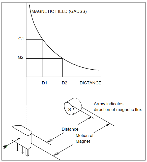
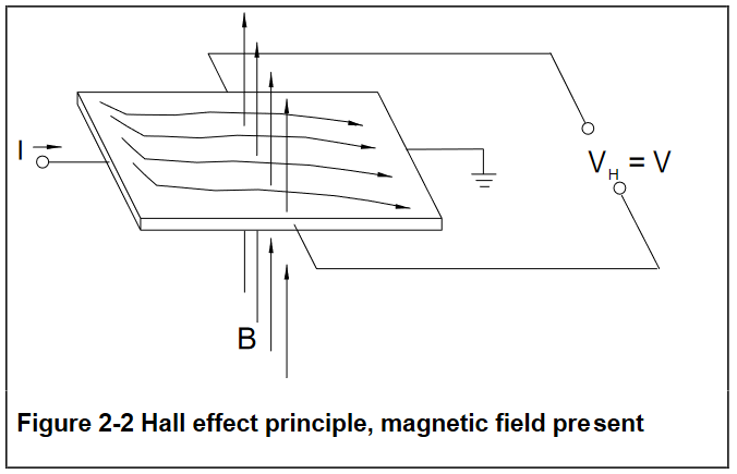
A fantastic resource for understanding hall effect sensing has been written by Honeywell Sensing if you are interested in digging deeper on the subject.
I will be operating the sensors in a modified “head on” orientation where in the distance between the magnet and sensor increases in conjunction with a rotation of the magnet itself.
The strength of the magnetic field is already proportional to 1/(distance^2) (the classic inverse square law), but I believe that the response seen by the sensors in my application will have a more severe response as the rotation of the field will cause the field lines to become increasingly parallel to the hall element, further reducing the influence of the magnetic field on the current passing through the hall element.
For the time being I will linearize my data as though it followed the inverse square law perfectly, but I may want to implement a lookup table approach if I am able to create a repeatable test setup to find the response to the motion present in the fingers
Splay
I plan to hold off on detecting finger splay until I have the finger flexion sensing operational. I have a feeling that the hall effect sensing can be recycled here, though we will see how that goes.
Data Handling
For handling the data provided by each sensor on the finger, I will be using a PJRC Teensy 4.0 microcontroller. I have used Teensy in the past and the performance per dollar is astounding. There are several reason I’ve chosen this microcontroller over others:
- I am already very familiar with the arduino environment, meaning there will be no additional learning required to get the system running
- The Teensy runs off 3.3V, the same as the SteamVR HDK I intend to use
- The high clock speed will allow me to filter incoming ADC readings to smooth out operation of the glove
- The physical size of the microcontroller lends itself to being mounted on the back of my hand
- The 14 onboard 10-bit ADC channels will be nearly perfect if using sensors for two knuckles per finger and distance between fingers
The purpose of the Teensy in this case is to retrieve the analog signals provided by the finger sensors and wrangle them in to a format that can be periodically transmitted to the SteamVR controller using its internal SPI bus. I have been unable to find documentation about the proper use of this SPI bus and my efforts to contact engineers at both Tundra Labs and Valve directly have not been successful. We will see how it goes.
SteamVR Tracking & Input
Since I want these gloves to operate as a standalone controller, I must implement SteamVR tracking directly in to them. To do this, I have ordered a Tundra Labs TL448K6D hardware development kit.
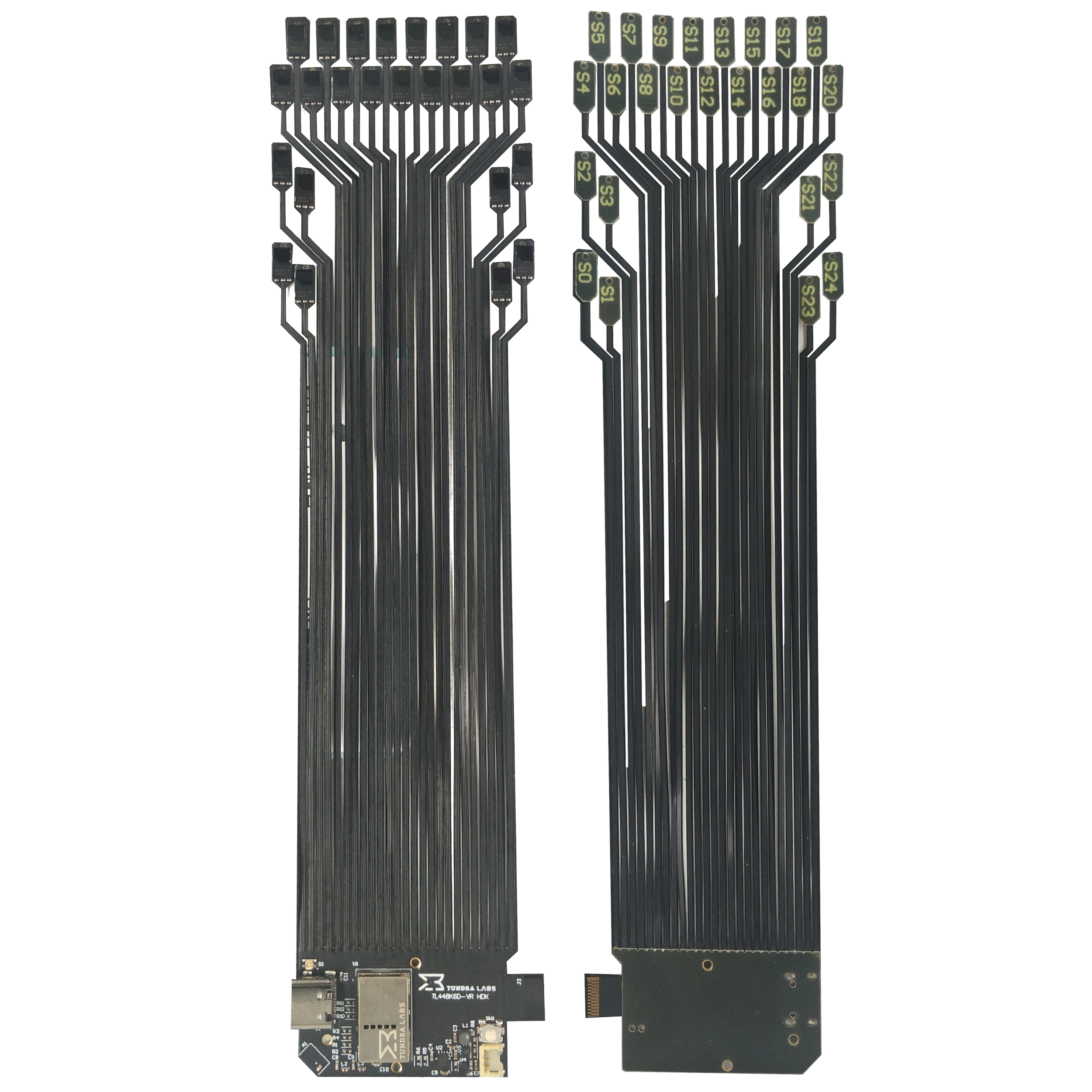
This HDK includes everything needed to create a basic SteamVR tracking puck. Their TL448K6D system-in-package contains the FPGA, MCU, and Radio controller needed to create a controller while the rest of the HDK includes:
- 2.4GHz Antenna
- RGB LED
- SteamVR System Button
- MP2667 1A Battery Charger & Power Path
- BQ27421YZFR-G1A Gas Gauge
- USB Type-C connector
- 25 Triad TS4112 Rev B Optical Sensors
- 25pin FPC connector for Input/Output (IO) expansion.
Unfortunately their datasheet does not go in to detail about the usage of the external I/O connector, so I plan to make a breakout board and tool around with it once the HDK arrives.
Once I have settled on a configuration for each part of the system, I plan to design a custom set of boards to integrate the sensors a bit more confidently and remove excess wires. It’s ok for my gloves to look like a prototype up until they start working reliably, then they must start looking like a finished product.
2025 Project Status
Project hit a stone wall when it came to implementing it as a tracked object. Unfortunately lighthouse appears to be end-of-life & there is not much sense in reinventing the wheel. Maybe next time!